1. INTRODUCTION
The use of timber, recognized as a carbon sink, as a construction material is becoming increasingly prominent worldwide in an effort to meet greenhouse gas emission reduction targets within the construction sector. In particular, wood-based construction materials exhibit reduced energy consumption during the manufacturing, processing, and transportation stages when compared with cement and steel, which are the most commonly used construction materials in Korea (Kwon et al., 2024; Seo et al., 2016). Timber construction, known for its climate change mitigation benefits due to low carbon emissions (Hafner and Schäfer, 2018; Pang and Oh, 2023), is experiencing a surge in demand worldwide (Chang et al., 2017).
Timber construction refers to building in which the primary structural members are composed of timber or wood-based material. In timber construction, structural members must demonstrate predictable load-bearing capacity to enable effective structural design.
Large or high-rise timber structures require long-span beams or large-section columns. The advent of structural engineered timber, characterized by an augmented cross-section and length, has engendered the feasibility of large, high-rise timber structures (Kwon and Kim, 2020). Typical structural engineered timbers include glued laminated timber (GLT) and cross laminated timber (CLT). The enhancement of the strength performance of structural engineered timber is essential for expanding the flexibility of timber construction design.
In order to construct long-span timber structures, such as classrooms or auditoriums, it is necessary to use bending members or bending resistance systems that can sufficiently support bending loads and minimize deflection in long spans (Kim et al., 2010). The bending members utilized in long spans are often designed through an enlargement of the cross-sectional dimensions, specifically the width and height, of the material. However, there are cases where the height of bending members cannot be increased as desired due to increased costs, interior space restrictions, or aesthetic considerations. Additionally, structural engineered timber may not perform as required in terms of bending performance. In such cases, the necessary performance can be attained by employing a hybrid structure that integrates timber with other materials. Therefore, the development of a bending load support structure employing a mixed structure is imperative, and research in this area has been conducted accordingly (Winter et al., 2016).
Hybrid structures suitable for supporting heavy loads in long spans can be designed by combining the advantages of timber and steel (Khorasani, 2011). In essence, the integration of engineered timber, characterized by its low buckling and exceptional compressive load-bearing capacities, with steel, which possesses outstanding tensile load-bearing capacities, enables the design of hybrid structures that exhibit remarkable load-bearing capacity. Hybrid structures offer the advantages of being able to extend spans, reduce cross-sectional areas, and be designed in a variety of shapes (Lee and Jang, 2023; Wang et al., 2021).
This study aims to assess the feasibility of replacing large-section GLT with a hybrid inverted king-post timber truss that utilizes the advantages of both timber and steel. Furthermore, the stress concentration locations and load-bearing mechanisms of the hybrid inverted king-post timber truss have been analyzed in accordance with the increase in load, and the load-bearing capacity has been improved based on a quantitative evaluation of the load-bearing capacity of the truss structure.
2. MATERIALS and METHODS
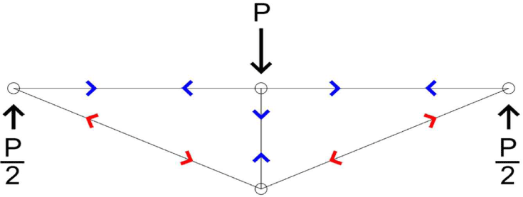
The hybrid inverted king-post timber truss uses GLT for the top chord to support only compressive loads and steel tension bars for the bottom chord to support only tensile loads. It was designed in the form of an inverted king-post truss that supports bending loads (Fig. 1). The connection points of the truss members were assumed to be pin joints. The compressive and tensile loads acting on the top and bottom chords were calculated using truss analysis based on the size of the central concentrated load and the length of the central vertical web.
The load design of the truss structure was calculated based on the compressive allowable stress of the same grade GLT (10S34B) specified in KS F 3021, ensuring that the compressive allowable stress acts on the top chord. The tensile stress of the bottom chord and the compressive stress of the vertical web members were calculated for the concentrated load (73.5 kN) applied to the center. The axial forces acting on each member shown Table 1 were calculated using Equations (1), (2) and (3).
| Vertical web height (mm) | P (kN) | Top chord (kN) | Bottom chord (kN) | Vertical web (kN) |
|---|---|---|---|---|
| 150 | 73.5 | (–)515.2 | (+)516.5 | (–)73.5 |
| 300 | 73.5 | (–)257.3 | (+)259.9 | (–)73.5 |
Where, P: applied load (kN), FWeb: axial force in the vertical web member (kN), Ftopchord: axial force in the top chord (kN), Fbottomchord: axial force in the bottom chord (kN), θ: angle between the top chord and the bottom chord (°).
GLT was produced using domestically grown Japanese larch (Larix kaempferi). GLT was manufactured using E11 grade Japanese larch laminate in accordance with KS F 3021, and four layers of GLT (10S34B) of the same grade were produced using phenol resorcinol formaldehyde resin, applied amount of 250 g/m2 and under a pressure of 11.8 MPa (Table 2).
| Specimens | Species | Size (mm) | Number of layers |
|---|---|---|---|
| GLT (control) | Larix kaempferi | 140 × 150 × 4,460 | 4 |
| Inverted truss top chord A (15) | 140 × 75 × 4,200 | 2 | |
| Inverted truss top chord B (30) |
Subsequent to the GLT bending test, moisture content specimens (20 × 20 × 20 mm) and specific gravity specimens (20 × 20 × 30 mm) were obtained from the undamaged area in proximity to the failure location. The moisture content and specific gravity of these specimens were then measured, according to KS F 2199, “method of determining the moisture content of wood,” and according to KS F 2198, “method of determining the density and specific gravity of wood.” The weight was calculated by multiplying the volume of GLT by its specific gravity.
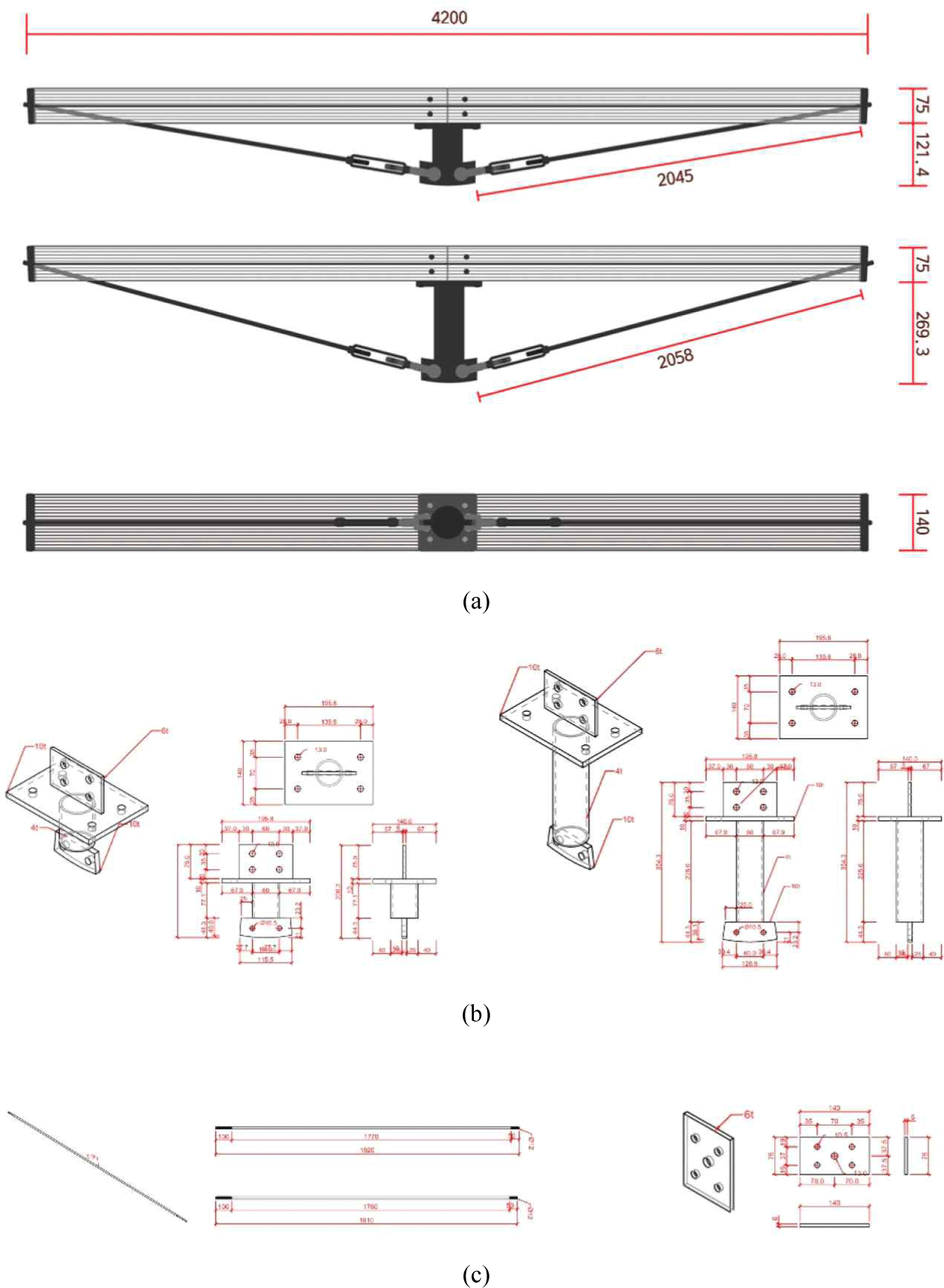
The hybrid inverted king-post timber truss structure was constructed in two types, with the height of the central vertical web members set at 150 mm and 300 mm [Fig. 2(a), 2(b)]. In the hybrid structure, the height of the vertical web member was set to 150 mm, the same as the control GLT, and 300 mm was set to achieve bending capacity equal to or better than the control GLT. The hardware components used in the specimens were vertical web members (SS275, 60 mm in diameter, 4 mm in thickness, and 206.300 mm and 354.300 mm in length), turnbuckles (SS275 12.700 mm and STS304 15.875 mm in diameter), tension bars (SS275 12 mm in diameter and STS304 16 mm in diameter), and side hardware (SS275 140 mm in width, 6 mm in thickness, and 75 mm in height; Fig. 2c; Table 3 and 4).
The vertical web members and GLT beams of the top chord were secured by cross-arranging hex screw bolts and drift pins. The side hardware and tension bar at both ends of the member are fastened with wood screws, and the tension bar is fixed with two nuts after passing through the side hardware. The joints of the hybrid inverted king-post timber truss were as shown in Fig. 3.

The specimens were five inverted king-post timber truss A specimens, five inverted king-post timber truss B specimens, and five GLT specimens as a control, for a total of 15 specimens. The total weight of hardware used in the production of inverted king-post timber truss A(15) and B(30) specimens was 10.47 kg and 11.33 kg, respectively. The characteristics of each specimen were as shown in Table 5. The total weight of the GLT of the top chord and the hardware of the bottom chord of the hybrid inverted king-post timber truss B(30) was 32.50 kg, which was approximately 19.29% lighter than the weight of the GLT (40.27 kg).
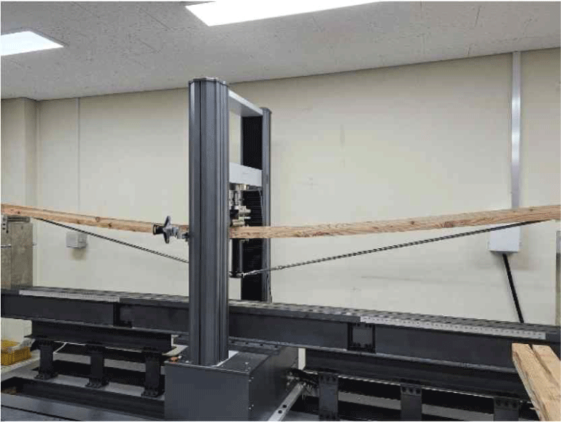
The bending test was conducted using RB 301 Unitech-M (R&B, Daejeon, Korea) in accordance with the KS F 3021 GLT Type B bending test (3-point load test; Fig. 4).
The span was adjusted from 3,600 mm to 3,960 mm to avoid interference with the load-bearing point of the bottom chord tension bar of each specimen and was tested to failure at a loading speed of 10 mm/min. The displacement was limited to 300 mm, which was the test limit of the testing machine (Table 6).
The modulus of rupture (MOR) and modulus of elasticity (MOE) were calculated using Equations (4) and (5). The cross-section for the calculation of MOR and MOE of the hybrid inverted king-post timber truss was calculated by applying the cross-sectional area of the control GLT to facilitate the comparison with the control.
Where, Pm: maximum load (N), L: span length (mm), b: specimen width (mm), h: specimen thickness (mm), Pe: proportional limit load (N), △e: proportional limit displacement (mm).
3. RESULTS and DISCUSSION
The mean moisture content was 8.24 ± 0.33% for the GLT that were subjected to the bending test, 7.55 ± 0.57% for the top chord GLT of A(15), and 7.82 ± 0.71% for the top chord GLT of B(30). The oven-dry specific gravity of the GLT was 0.43 ± 0.06, with a weight of 40.27 kg. The average oven-dry specific gravity of A(15) was 0.46 ± 0.06, and its weight of 20.29 kg. While the average oven-dry specific gravity of B(30) was 0.48 ± 0.04, with a weight of 21.17 kg.
The bending performance of the GLT was compared with that of the hybrid inverted king-post timber truss (Fig. 5).
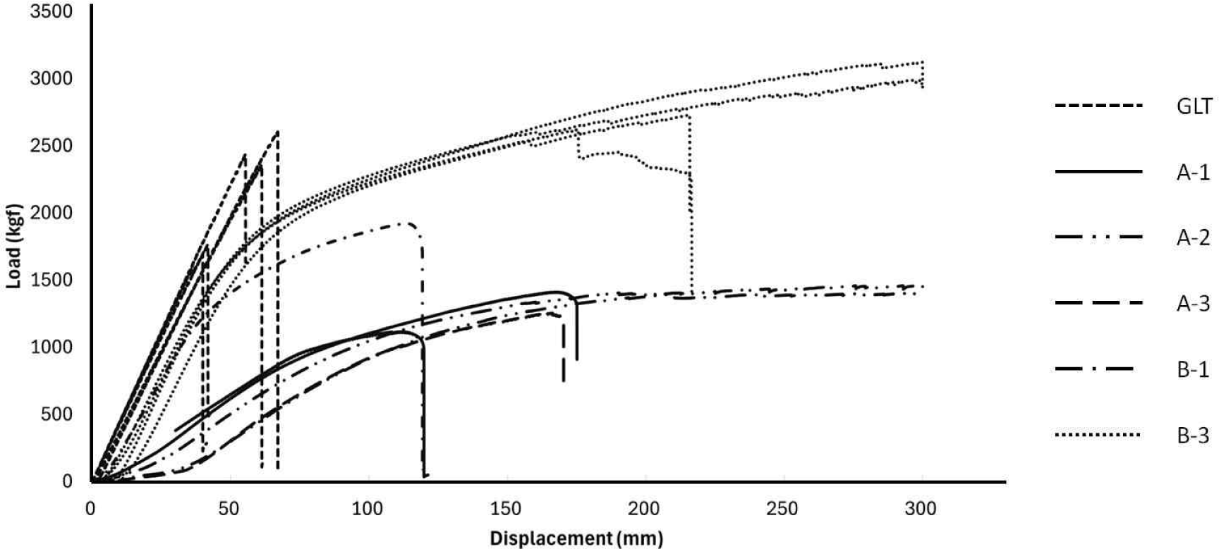
The load-displacement curve of the control group, GLT, showed a nearly linear brittle failure behavior from the initial loading phase to rupture. All GLT were observed to fail due to tensile stress occurring in the outermost tensile laminate immediately after reaching the maximum load. The GLT were measured to have an ultimate load of 21.29 ± 4.07 kN, a bending modulus of 10.38 ± 0.48 GPa, and a MOR of 36.49 ± 6.99 MPa.
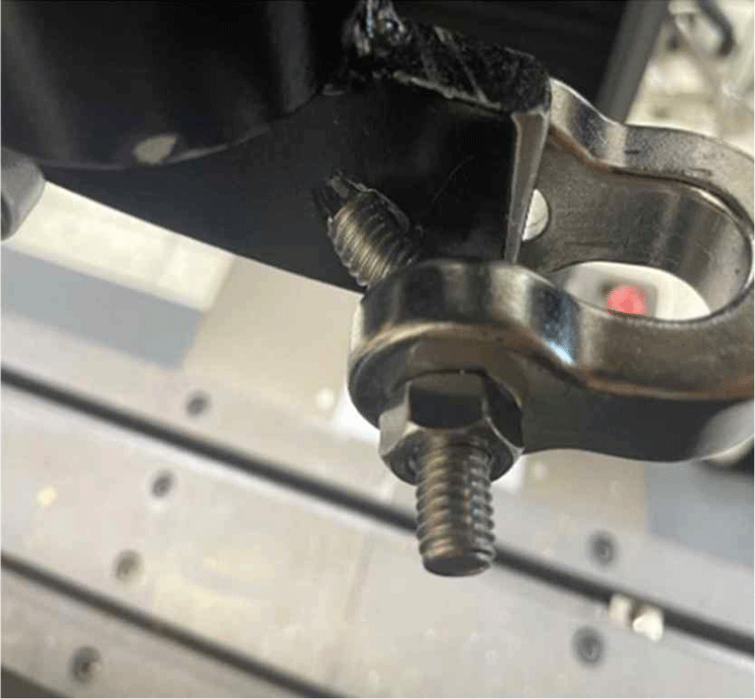
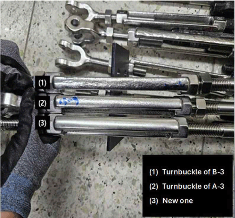
The hybrid inverted king-post timber truss maintained a gentle slope after reaching the maximum load. Ductile behavior was observed in the form of a constant increase in bending strain while the load did not increase. In a hybrid inverted king-post timber truss, the tensile load acting on the lower chord tension bar caused tensile deformation due to plasticity after the yield zone beyond the elastic zone, which was determined to be indicative of the plastic behavior of the truss system (Mei et al., 2021). In A-2-a, bending failure occurred at the anchor bolt inside the turnbuckle (Fig. 6). The turnbuckle body was found to have stretched longitudinally by approximately 0.7 cm in A-3 [Fig. 7(2)] and by 1.5 cm in B-3 [Fig. 7(1)].
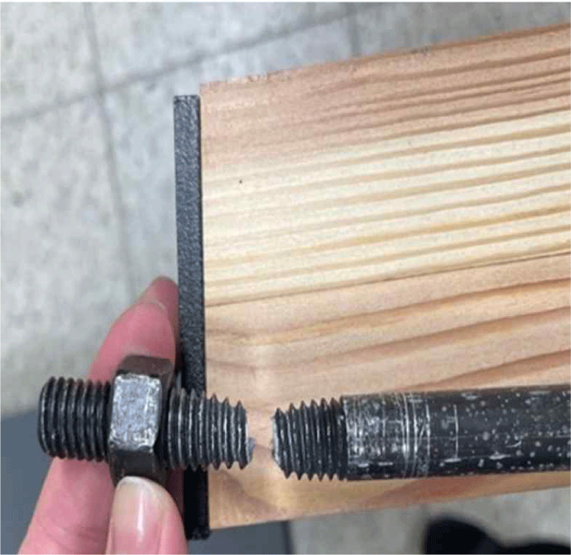
In A-1 and B-1, tensile plastic deformation occurred in the threads of the bottom chord tension bar joint, ultimately leading to tensile failure (Fig. 8). The threads in the bottom chord tension bar joint of the hybrid inverted king-post timber truss may have reduced the effective cross-sectional area of the tension bar, leading to a concentration of tensile stresses that caused the failure.
The tensile stress and failure behavior of the bottom chord tension bar under bending load were as shown in Table 7. For A-1, where the failure occurred in the threads of the bottom chord tension bar joint, the MOE was 3.47 ± 0.36 GPa and the MOR was 21.23 ± 3.50 MPa. Compared to the control GLT, the MOE was 33.43% lower and the MOR was 58.18% lower. The hybrid inverted king-post timber truss supporting bending loads experienced plastic deformation and tensile failure due to tensile loads at the threaded parts of the bottom chord tension bar and the turnbuckle. The tensile performance of the bottom chord tension bar was not designed to sufficiently support the tensile loads acting on the bottom chord of the hybrid inverted king-post timber truss. In order to improve the tensile load-bearing performance of the bottom chord tension bar, the diameter of the tension bar was increased from 12 mm to 16 mm and the turnbuckle was increased from 12.700 mm to 15.875 mm (A-2). The results showed that the MOE of A-2 was 3.72 GPa and the MOR was 21.07 MPa, which were 35.84% and 57.74% smaller than the control GLT, respectively. For A-2, tensile plastic deformation was also observed in the turnbuckle. Therefore, the diameter of the connection bolt was increased from M10 to M12 to fabricate the A-3 specimen.
The MOE of A-3 was 4.10 ± 1.04 GPa, and the MOR was 25.28 ± 2.41 MPa, which were 40% and 69% smaller than those of the control GLT, respectively. The tensile elastic performance of the bottom chord was improved by increasing the diameter of the turnbuckle and applying a material with high rigidity and strength, resulting in a higher MOE. The bending performance of the hybrid inverted king-post timber truss was improved due to the increase in tensile yield strength.
Nevertheless, the short length (150 mm) of the vertical web members resulted in very high tensile loads acting on the lower chord tension bar, making it difficult to improve the bending performance of the hybrid inverted king-post timber truss through improvements in diameter and material.
In a hybrid inverted king-post timber truss where the length of the vertical web members was increased from 150 mm to 300 mm to reduce the tensile load on the tension bars, the MOR was 96% and the MOE was 108% for tension bars and turnbuckles of B-1, which was made of the same material as A-1, compared to the control. Therefore, B-3 experiments were conducted by reinforcing the diameter of the tension bar from 12 mm to 16 mm, the diameter of the turnbuckle from 12.700 mm to 15.875 mm and the turnbuckle connecting bolt dimensions from M10 to M12. B-3 showed a MOR of approximately 145 ± 30% and a MOE of approximately 124 ± 7% compared to the control group GLT.
The performance of hybrid inverted king-post timber trusses was found to improve as the length of the vertical web members increased (Kim et al., 2006; Mei et al., 2021).
The MOE was found to be high in hybrid inverted king-post timber truss B with a vertical web member length of 300 mm, and B-3 showed the highest MOE of 12.83 ± 0.39 GPa. In hybrid trusses, the performance of hybrid structures can be improved by evenly distributing the load supported by each member or by using materials with high strength and stiffness in members where the load is concentrated (Chesnokov and Mikhailov, 2024).
Plastic deformation occurs beyond the elastic zone in the hybrid inverted king-post timber truss. The top chord GLT beam supporting the compressive load is made of a highly elastic material (Jang et al., 2009). In particular, for compressive loads parallel to the grain direction, the allowable design load can be supported as long as buckling does not occur, and compressive failure parallel to the grain direction is a brittle failure (Branco et al., 2010). Therefore, plastic deformation due to bending loads in hybrid inverted king-post timber trusses appears as plastic deformation in the bottom chord tension bar members. The tensile load acting on the bottom chord tension bars increases in proportion to the increase in the bending load applied to the truss.
In this study, the tension bars were made of carbon steel SS275 and alloy steel STS304, respectively (Table 4). Depending on the characteristics of the metal material, permanent deformation occurs due to plastic deformation when the yield strength of the material is exceeded. In the plastic zone, metal materials support tensile loads and undergo plastic deformation, causing ductile behavior in hybrid trusses (Kim et al., 2006; Mei et al., 2021). The turnbuckle, tension bar, and turnbuckle fixing bolt are within the same tension system and therefore undergo the same tensile force. To determine the tensile force acting on the tension bar, the member forces of each truss element were examined using Equations (6) and (7). The loads acting on vertical web members were analyzed by applying the loads generated in the flexible behavior of hybrid beams.
Where, T: tensile force of the tension bar (N), P: load at the start of the plastic deformation zone (nonlinear region; N), θ: angle between the horizontal member and the tension bar (°), σT: tensile stress acting on the tension bar (MPa), A: cross-sectional area of the tension bar (mm2).
The analysis results of the tensile load acting on the tension bar of the hybrid inverted king-post timber truss are presented in Table 8. The vertical load P is the load at the start of the plastic deformation zone of the hybrid inverted king-post timber truss in the bending test, and the tensile load applied to the tension bar at that load was calculated.
An analysis of the tensile forces acting on the tension bar under A-1 and B-1 conditions for SS275 material with a diameter of 12 mm predicted failure or plastic deformation at relatively low loads. A-1-a had a tensile stress of 443.20 MPa at a bending load of approximately 7.56 kN, which exceeded the tensile strength of SS275 (approximately 410 MPa), and failed at the threads of the tension bar. In A-1-b, the tensile stress of 310.62 MPa at a bending load of about 5.30 kN exceeded the yield strength of SS275 (about 275 MPa), and in B-1, the tensile stress of 279.02 MPa at a bending load of 9.12 kN exceeded the yield strength, and plastic deformation was predicted. However, failure occurred at the threads of the tension bar joint. This may have been attributed to the fact that SS275 has a lower yield strength, tensile strength, and elongation than STS304, and the machining of the threads resulted in localized stress concentration due to the small diameter of the tension bar.
In the A-2, A-3, and B-3 conditions, with STS304 of 16 mm in diameter, the elastic and plastic deformations were predicted at high loads. The tensile stresses of A-2-a and A-3-b were calculated to be approximately 147.10 MPa and 183.94 MPa at bending loads of 4.46 kN and 5.58 kN, respectively, and did not exceed the yield strength of STS304 (approximately 205 MPa), indicating elastic behavior. For B-3-a and B-3-b, tensile stresses of 250.69 MPa and 232.85 MPa at bending loads of 14.57 kN and 13.53 kN, respectively, were predicted to exceed the yield strength, resulting in plastic deformation. For B-3-c and B-3-d, the tensile stresses were 161.67 MPa and 188.54 MPa at bending load of 32.50 kN and 10.96 kN, respectively, which did not exceed the yield strength of STS304 (approximately 205 MPa), and elastic behavior was predicted. This may have been caused by the high tensile strength of STS304 and the relatively large cross-sectional area of the tension bar, which increased the load distribution capacity and stiffness.
The section moment of inertia (I) and section modulus (S) of the GLT beams used in the hybrid inverted king-post timber truss and the control GLT beams were calculated using Equations (8) and (9).
Where, b: beam width (mm), h: beam thickness (mm).
The calculated cross-sectional performance results of the GLT beams used in the hybrid inverted king-post timber truss and the control GLT beams are presented in Table 9. The GLT employed in the hybrid inverted king-post timber truss exhibited the capacity to perform on par with or even surpass the performance of the GLT, despite the fact that its section moment of inertia (I) was 12.5% lower and its section modulus (S) was 25% lower than that of the control GLT.
| Sample | Section size (mm) | I (mm4) | S (mm3) | Ratio (%) |
|---|---|---|---|---|
| GLT (control) | 140 × 150 | 39,375,000 | 525,000 | 100 |
| Inverted truss beam | 140 × 75 | 4,921,875 | 131,250 | 12.5% (I) / 25% (S) |
The length of the vertical web members of a hybrid inverted king-post timber truss will affect the load distribution acting on the bottom chord tension bar. Failure or plastic deformation was predicted for A, where the vertical web member was 150 mm long, but elastic or plastic deformation was predicted for B, where it was 300 mm long, even at high loads. In particular, B-3-a had the highest maximum bending load of 14.57 kN, demonstrating excellent bending performance. The increased the height of vertical web member improved the load-bearing capacity of the hybrid inverted king-post truss, securing its rigidity and structural safety.
In order to maximize the bending load-bearing capacity of the hybrid inverted king-post timber truss, the following conditions were considered: 1) increasing the height of the vertical web members and 2) meeting the maximum tensile strength of the bottom chord tension bar when the maximum compressive strength of the top chord GLT was reached.
4. CONCLUSIONS
This study analyzed the bending load support capacity and behavior of a hybrid inverted king-post timber truss supporting bending loads according to the characteristics of its structural members and drew the following conclusions.
Hybrid inverted king-post timber truss B-3-a, with improved material and diameter of the bottom chord tension bar, had the highest values for maximum bending load, MOE, and MOR, indicating its potential for use as a structural member. The utilization of the hybrid inverted king-post timber truss as a structural member to support bending loads is expected to facilitate efficient use of resources by reducing the amount of timber required. Furthermore, the reduced thickness of the GLT beams will allow for an aesthetic ceiling height difference that will significantly improve the space efficiency of the structure.
The way to maximize the performance of a hybrid truss is to design the system to properly distribute the loads acting on the entire structure to each member, with each member designed to support the maximum load acting on that member. In particular, this study has presented the possibility of utilizing hybrid timber trusses with GLT utilizing domestic small- and medium-sized timber for large high-rise timber structures that are subjected to high loads.


