


1. INTRODUCTION
Wood has been used in furniture-making and construction since the prehistoric ages as it is a natural material and easily sourced. In Korea, many historic properties are built of wood (Lee and Bae, 2021; Lee et al., 2021; Nam and Kim, 2021). The conservation of these historic wooden properties is crucial to delivering them to the next generation (Kim et al., 2012). A method is required to investigate the inner state of wooden properties to conserve historic properties appropriately (Oh et al., 2019). Non-destructive testing and evaluation (NDT &E) methods are normally used to determine the interior structure of wooden properties (Kim et al., 1996; Kim et al., 2003; Lee et al., 2003; Maulana et al., 2019; Pang and Jeong, 2019).
There are many reports on the occurrence of biological deterioration, such as termite damage (Lee et al., 2020; Mun and Nicholas, 2017; Son and Lee, 2008), in historic wooden buildings. However, the size of the termite damage is too small to be detected using acoustic or ultrasonic methods, which are normally used in wood conservation. To the best of our knowledge, reconstructed computed tomography (CT) of radiation is the best way to detect the inner state of wood (Hwang et al., 2020). When CT is applied to a historic wooden member, its result can provide the density profile or existence of even minute deterioration without having to demolish the entire building. However, evaluating the inner state of wooden columns surrounded by walls is difficult with CT because the apparatus of CT cannot rotate enough to gain projections for reconstructing CT images, as shown in Fig. 1. Therefore, different NDT&E techniques using X-ray radiography are needed to overcome the limitations of CT.
In this study, tomosynthesis was applied to find an alternative method for investigating the inner state of wooden columns surrounded by walls. With the development of radiation measurement technology, tomosynthesis has drawn attention again in the medical field (Andersson et al., 2008; Ciatto et al., 2013; Dobbins and Godfrey, 2003). It can reconstruct an arbitrary cross-section (coronal section) using a few projections from a limited angle along a single-acquisition sequence. However, tomosynthesis is rarely studied in wood science.
We conducted a feasibility study of tomosynthesis on a wooden column surrounded by walls. In addition, radiography parameters such as the rotation angle and number of projections were tested, and an optimal condition of radiography was found by evaluating the reconstructed in-focus plane tomosynthesis image quality and quality of the vertical resolution.
2. MATERIALS and METHODS
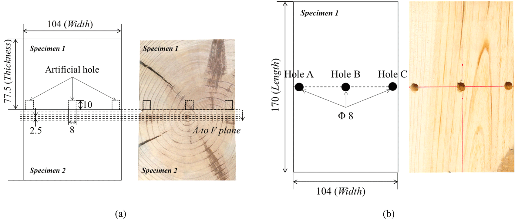
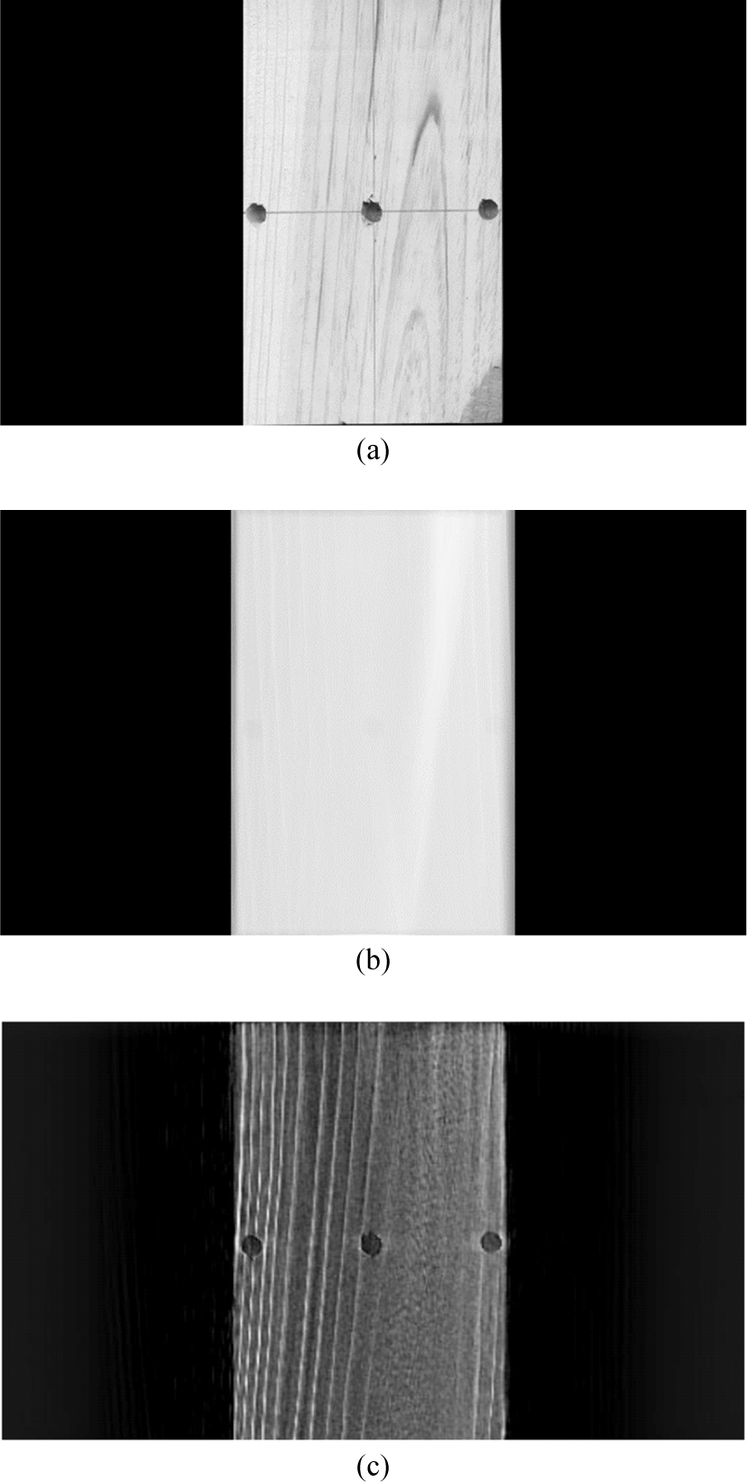
Two pine (P. densiflora) lumbers having a cross-section size of 104 (width) × 77.5 (thickness) mm2 and a length of 170 mm were used as specimens for this study. Pine is one of the commonly used wooden species for historical building construction in Korea. By using the oven-dry method, the average air-dry density and moisture content of the small specimens were brought to 0.41 g/cm3 and 15.2%. Three artificial holes of 8 mm diameter each were made in an early wood tangential cross-section of one pine specimen to determine the optimal radiography condition for tomosynthesis. These holes were made to describe the shape of termite damage, which is mainly found in early wood. The depth of the holes was 10 mm. The detailed information on the specimens is shown in Fig. 2.
The X-ray tube, K-4 (Softex, Kobe, Japan), was used to radiate X-rays. The maximum tube voltage and current of the X-ray tube are 64 kV and 5 mA, respectively. From the results of a preliminary test, a tube voltage of 45 kV and a current of 5 mA were chosen to emit the X-rays. EVS 4343 (DRtech., Seongnam, Korea) was employed as a detector to obtain projections, and its spatial resolution was 3.5 line pair per millimeter (lp/mm). One projection was obtained by exposing the detector for 1.2 s to the X-rays. All projections during tomosynthesis radiography were directly saved in DICOM format on a laptop.
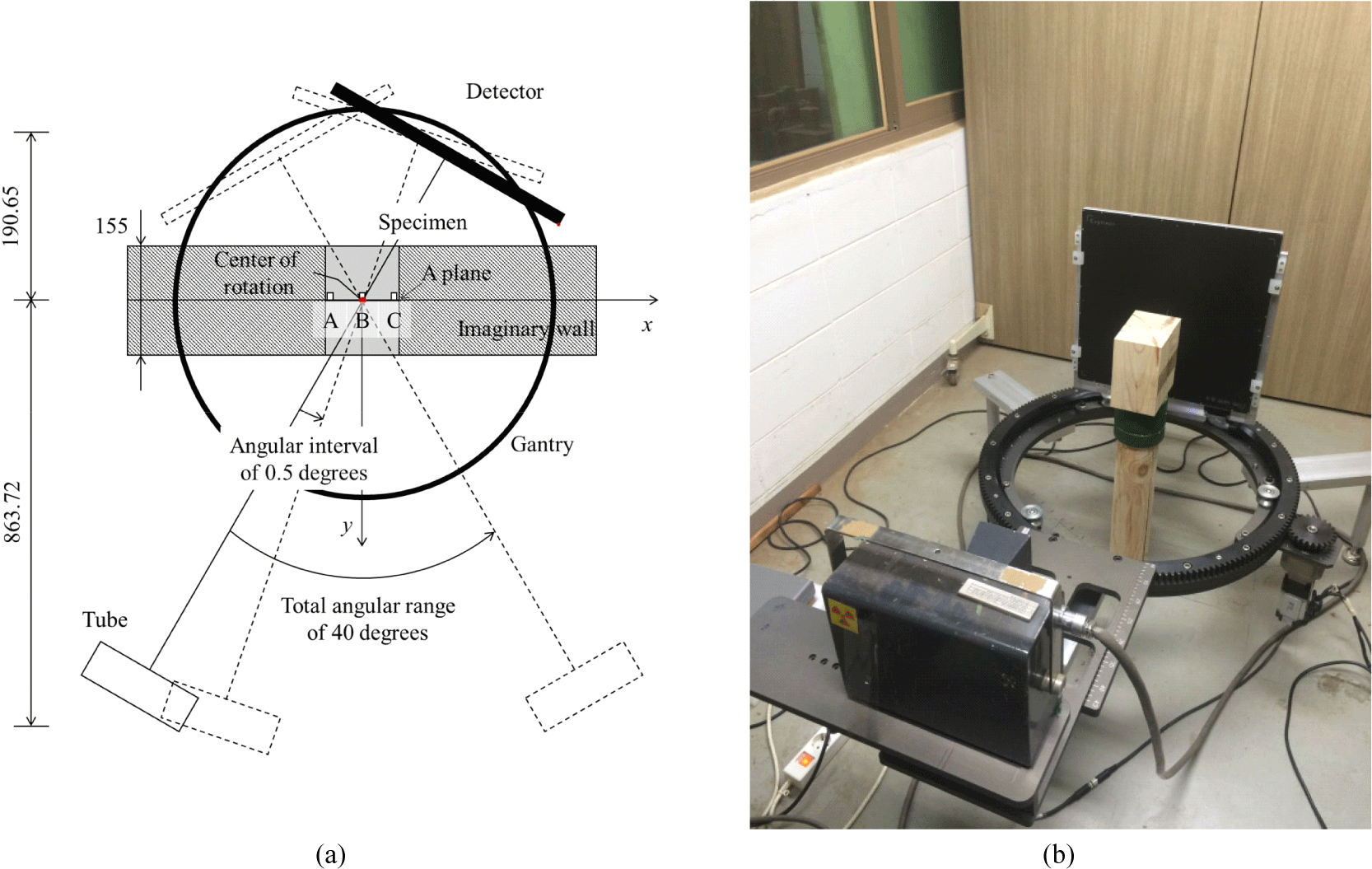
The complete isocentric motion method, in which the tube and detector were concurrently rotated at a certain angular interval, was conducted to obtain projections. A distance of 1,054.37 mm between the tube and detector was maintained during the test. The limited total angular range of 40 degrees was determined to gain projections for reconstructing images considering an imaginary wall of 155 mm thickness and tomosynthesis apparatus. The specimens were placed at the rotation center of the gantry during gaining projections. The detailed isocentric motion method is shown in Fig. 3.
The X-ray tube and detector were simultaneously rotated at an angular interval of 0.5 degrees to obtain projections for reconstructing tomosynthesis images. The obtained 81 projections were divided into six sets according to the angular interval of 0.5, 1, 2, 2.5, 4, 5, and 8 degrees. The number of projections for six sets for the angular intervals of 0.5, 1, 2, 2.5, 4, 5, and 8 degrees was 81, 41, 21, 17, 11, and 9, respectively. Projections for the six sets were reconstructed using a filtered back-projection algorithm with cone-beam and flat-panel detector geometry (Badea et al., 2001). In the filtered back-projection algorithm, the Ram-Lak filter was applied to remove blurs in the reconstructed images.
Contrast-to-noise ratios (CNRs) (Zhang et al., 2006) between the three artificial holes and sound wood were computed to evaluate the quality of the reconstructed tomosynthesis image of the in-focus plane, which is located at y = 0 in Fig. 3. The CNR value could be calculated by using Equation (1) as follows:
Where is the average pixel grayscale of the signal region of interest (ROI), is the average pixel grayscale of background ROI, and σ is a standard deviation of the signal ROI. Here, the signal and background ROI indicate an average pixel grayscale for the artificial hole and wood around each hole in the reconstructed image at the A plane. Each ROI was defined as a 3 × 3-pixel square, and the number of signals and background ROI was 25. The effect of different radiography conditions on CNR was analyzed by normalizing each CNR value by dividing them by the maximum CNR.
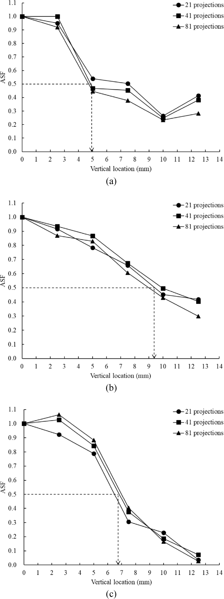
Wu et al. (2004) introduced an artificial spread function (ASF) to measure image blur in the vertical direction (y-direction) or quality of vertical resolution of the reconstructed images. ASF is defined as a ratio of the CNR values between the off-focus planes [planes from B to F in Fig. 2(a)] and the in-focus plane [A plane in Fig. 2(a)].
where y0 is the location of the in-focus plane, and y is the location of out-of-focus planes. Each calculated ASF was fitted to a polynomial function according to the vertical location in the y-direction. The vertical location in the y-direction, where the maximum ASF is 0.5, was used to determine the quality of vertical resolution for each set of projections. As the vertical location in the y-direction gets smaller, the quality of vertical resolution is better.
3. RESULTS and DISCUSSION
Fig. 4 shows the normalized CNR of the in-focus plane (A plane) according to the location of the hole for each set via the number of projections. The normalized CNR value increased and became constant as the number of projections increased. The constant number of the normalized CNR value was about 0.8. There was no significant difference above the normalized CNR of 0.8 when the reconstructed tomosynthesis images were compared with each other. Meanwhile, even when the same number of projections were used to reconstruct the tomosynthesis image, the normalized CNR value differed according to the location of the hole. It was confirmed that more projections were needed to obtain a normalized CNR of 0.8 or more for holes A and C, which were located at the edge of the specimen. Once termites enter the wooden walls through the foundation, they cause more deterioration at the edge of the members (where there is high moisture contact with walls) than at the center of the members. Therefore, it was reasonable to determine the optimum radiography condition for the in-focus plane based on the CNRs of Hole A or C. In this test condition, a set of 21 radiographs was chosen to reconstruct tomosynthesis images.
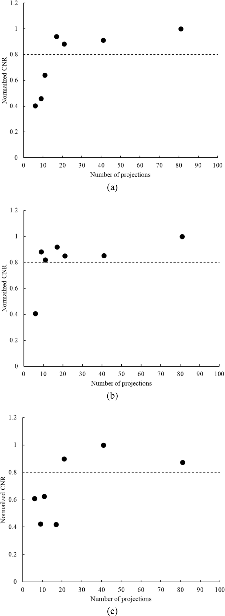
Fig. 5 shows an actual picture of the specimen, single projection, and tomosynthesis image, reconstructed using 21 radiographs obtained at a 40 degrees angular range in the in-focus plane. In the case of the single projection, detecting the size or location of holes was challenging because of the superposition of specimen’s information. However, the tomosynthesis image could be used to investigate the inner state of wood, as shown in Fig. 5(c). The tomosynthesis image was quite similar to the actual picture of the specimen with regard to not only the information of the holes but also the inner state of the wood. Therefore, it was concluded that tomosynthesis has the advantage of examining the deterioration of the wood’s interior, such as minor termite damage.
In the medical field, many studies were conducted to find an optimal radiography condition to obtain high-quality reconstructed tomosynthesis images with the least radiation exposure for patients (Chawla et al., 2009; Lu et al., 2011; Sechopoulos and Ghetti, 2009). Sechopoulos and Ghetti (2009) reported that the highest quality tomosynthesis image at the in-focus plane could be reconstructed with 13 projections from an angular range of 60 degrees. In that study, there was no correlation between the number of projections and in-focus plane quality. This was inconsistent with our results. This is because the exposure time for one projection changed according to the number of projections due to dose limitations in a patient. Dose limitation for NDT&E methods for wood is rather liberal compared with that for medical usage. The exposure time for one projection can be maintained regardless of the number of projections. Therefore, the number of projections affected the quality of the tomosynthesis image in this study.
In previous studies, 21 projections for the angular range of 40 degrees were chosen to reconstruct tomosynthesis images with high accuracy. Therefore, 21 or more projections for reconstructing tomosynthesis images were employed to calculate ASF. Fig. 6 shows the results of ASF according to the number of projections, and Table 1 presents the vertical location in the y-direction, where the maximum ASF is 0.5. At the same vertical location in the y-direction, the number of projections did not significantly affect the quality of vertical resolution of reconstructed tomosynthesis images. On the other hand, the vertical location in the y-direction was influenced by the detection position. The average vertical location in the y-direction with a maximum ASF of 0.5 was 4.94, 9.37, and 6.74 mm for holes A, B, and C, respectively.
| Projection number | Vertical location in the y-direction (mm) | |||||
|---|---|---|---|---|---|---|
| Hole A | Hole B | Hole C | ||||
| 21 | 5.62 | 4.94* (0.12)** | 9.46 | 9.37 (0.06) | 6.44 | 6.74 (0.04) |
| 41 | 4.67 | 9.91 | 6.81 | |||
| 81 | 5.52 | 8.73 | 6.98 | |||
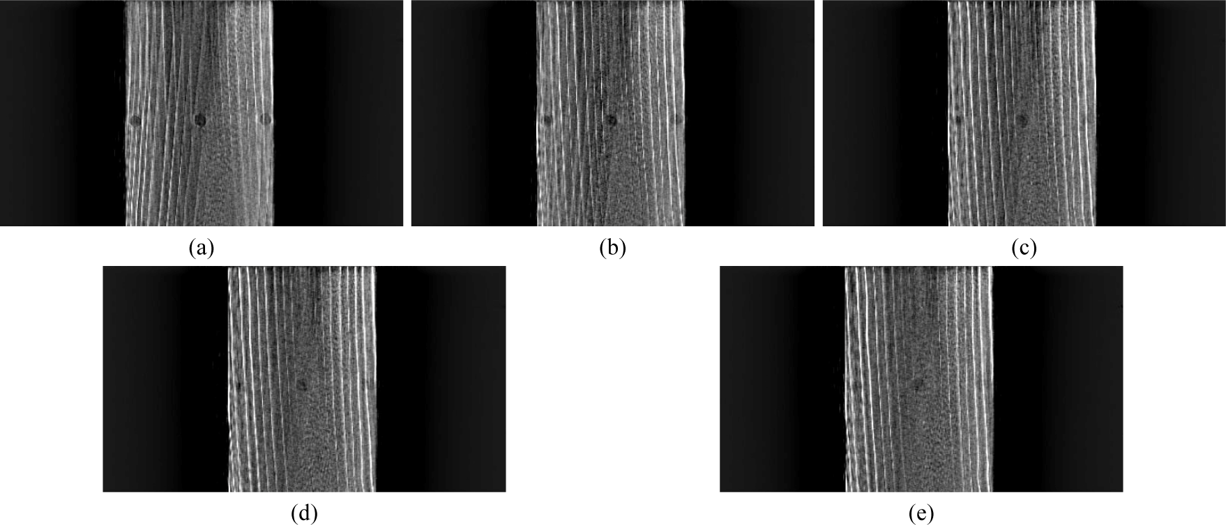
Fig. 7 presents the results of reconstructed tomosynthesis images in the vertical location of 2.5 mm or over using 21 projections. As shown in Fig. 6 and Table 1, there is noticeable blurring in the tomosynthesis images within a vertical location of less than 10 mm. Therefore, a distinct difference between the planes would be obtained when a distance of more than 10 mm was maintained from one plane to another with this radiography condition.
In this study, tomosynthesis was confirmed to be feasible for investigating the inner state of wood. Further studies will be conducted on the relation between angular range and vertical resolution of reconstructed tomosynthesis images. The existent blurring in tomosynthesis images is unavoidable because the total angular rotation in tomosynthesis is smaller than that in CT, in which the angle of rotation is at least 180 degrees. Research to improve vertical resolution in tomosynthesis images has been conducted in medical filed. The main method is to apply spatial resolution of the detector and a large angular angle to get more phase differences according to the movement of the apparatus. Zhao et al. (2015) reported a positive correlation between spatial resolution and the quality of reconstructed tomosynthesis images. They suggested a spatial resolution of 5 lp/mm to detect small microcalcifications in the breast, which is higher than that used for this study. There were also reports about the effect of angular angle on the quality of vertical resolution (Hu et al., 2008; Sechopoulos and Ghetti, 2009). According to these reports, the quality of vertical resolution increased as the angular range of the tomosynthesis apparatus increased. It is difficult to consider spatial resolution when applying tomosynthesis for the NDT&E of wood. Usually, a detector with a high spatial resolution is too small to be used to investigate historic wooden members. So, additional studies are needed to improve tomosynthesis image quality by determining an optimized angular angle for the NDT&E of wood.
4. CONCLUSIONS
Tomosynthesis was applied to find the optimal radiography condition for investigating the inner state of a wooden column surrounded by walls. The feasibility of tomosynthesis using 21 projections from an angular range of 40 degrees was confirmed. Damages, which occurred in the center and edge of the specimen in the in-focus plane, could be detected successfully with this method. The method used in this study has also used the vertical resolution to gain information on another plane that is 10 mm or over apart from the in-focus plane. This information can estimate the deterioration size or determine the repair scope for a wooden column. This study concluded that tomosynthesis could be a potential advanced method for conserving historical properties; however, more advanced X-ray radiography needs to be developed to examine a larger dimension of wood members.