1. INTRODUCTION
Log-wood and green lumber contain a substantial amount of moisture. If they are used without drying, dry defects arise, such as surface checking, twisting, and bowing. Therefore, wood should be dried to the in-use moisture content. However, the wood drying process consumes considerable energy and time. Hence, it would benefit from optimization. Such optimization necessitates theoretically and experimentally explaining the amount of energy input by the size of the wood, moisture distribution and temperature distribution inside the wood.
There have been many studies on the moisture transfer in wood (Siau, 1995). In wood, the water exists in three phases (free/liquid water, bound water, and water vapor) and the moisture is moved mainly through the free water flow above the fiber saturation point (Tiemann, 1921; Salin, 2006). Due to the formation of the moisture gradient, the diffusion of bound water moves through the cell wall, and the movement of water vapor occurs due to the relative vapor pressure gradient (Siau, 1995). Studies have been carried out to predict the moisture transfer in the range of moisture content below the fiber saturation point and to analyze the moisture transfer regarding the permeability of the wood cell wall and the pits (Kang et al., 2008; Stamm, 1960). Analysis of moisture transfer in wood during high temperature drying has been studied by Soma et al. (2013) and Cai (2010). However, there are few studies on moisture transfer in wood at temperatures above 100°C for domestic woods.
The finite difference method (FDM) is a robust numerical approach to solving the heat, moisture and mass transfer problem. The moisture transfer can be expressed as a finite difference, using the mass balance in the wood. The FDM method has been used for one-dimensional (Avramidis et al., 1994), two-dimensional (Schnabel et al., 2017; da Silva et al., 2014) and three dimensional (Salin, 2006; da Silva et al., 2011; da Silva et al., 2014; Younsi et al., 2006) analysis of changes of temperature or moisture content in wood during drying. The disadvantage of the FDM is that it is difficult to formulate irregularly shaped objects. However, it is relatively easy to analyze moisture transfer in square timber using the FDM because it is dried to stereotyped form shape.
High temperature drying is a method for rapidly drying wood at 100°C or higher, which can shorten the drying period by about 4 to 10 times compared to conventional kiln drying. However, during high temperature drying of wood with a large cross-section, the moisture gradient between the center of the wood and the surface becomes very high, which can lead to defects due to dry stress. Therefore, evaluating the moisture transfer within the wood during the high temperature drying is essential for the analysis of the internal stress distribution of the wood. In this study, the moisture transfer in boxed heart square timber of red pine was evaluated, during high temperature drying, by the three-dimensional FDM.
2. MATERIALS and METHODS
FDM was used to predict the internal moisture content of the wood. The governing equations for mass transfer in three dimensions can be expressed by Eq. (1), using the mass balance in the unsteady state.
where Dx = diffusion coefficient in x direction
(m2/s); Dy = diffusion coefficient in y direction
(m2/s); Dz = diffusion coefficient in z direction
(m2/s); C = mass concentration (kg/m3); x, y
and z = distance in the direction of flow (m),
and τ = time (s).
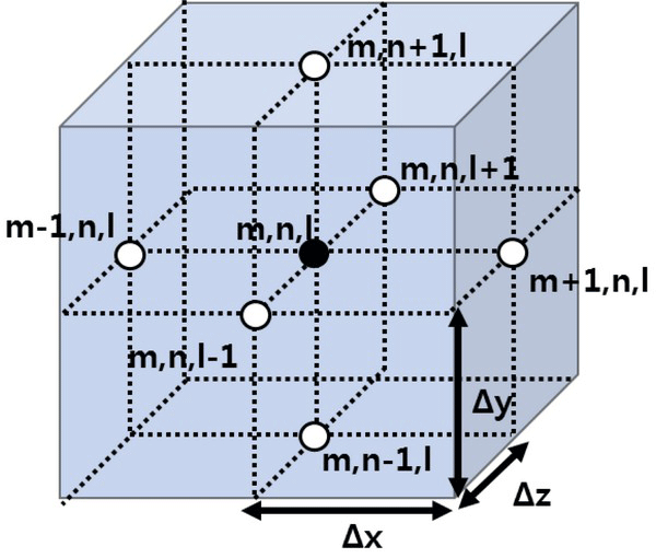
If the object is incremented in the x-, y-, and z-axis directions, the intersection can be designed as shown in Fig. 1. Furthermore, the derivative terms of Eq. (1) can be approximated as shown in Eq. (2)~(5).

where, m, n and l = number representing locations in each direction; p = number representing pth time, p+1 = (p+1)th time.
Therefore, when Eq. (1) is expressed in the finite difference form, the differential equation at the internal node inside the wood is as follows [Eq. (6)]:
The node of the surface, the edge and vertex of the wood is different from that described in Eq. (6), and the moisture is emitted from the surface of the wood to the ambient air. Thus, it can be added to the mass balance to design the equation. At the node, representing the outer surface boundary, where surface moisture emission occurs in one direction, we can formulate the following [Eq. (7)]:
where S = surface emission coefficient (m2/s); Ce = moisture concentration in equilibrium (kg/m3).
The mass transfer at the edge, where the moisture is emitted in two different direction can be expressed by Eq. (8).
The differential equation at the vertex node, at which water is emitted from three surfaces of an object, is shown in Eq. (9).
The moisture diffusion coefficient of the softwood was calculated by the geometric moisture diffusion model. This model is a modification of the electric circuit model of Stamm (1960), in consideration of the water vapor permeability in the pits and the rays (Kang et al., 2008). Fig. 2 shows the structure of water diffusion in the geometric moisture diffusion model. The moisture diffusion coefficient for each direction can be expressed as shown in Table 1. In the case of wood with a boxed heart, the radial direction and tangential direction are not fixed according to each node because the pith position is not constant. Consequently, the transverse moisture diffusion coefficient was determined, using the mean moisture diffusion coefficient of the radial and tangential directions. Assuming that the diameter of the tracheid (35 μm), the length of the rays (250 μm), and the size of the pits (1 μm) were constant, the ratio of pits to wood cells (p) and the ratio of rays to wood cells (r) were calculated, using the values measured by Eom (2015). The transverse bound-water diffusion coefficient of the cell wall (DBT), the diffusion coefficient of the water vapor in the air within the lumens (Dv), and the longitudinal bound-water diffusion coefficient of the cell wall (DBL) were determined by Eq. (10)~(13) (Siau, 1995).

where, DBT = transverse diffusion coefficient of bound water in the cell wall (m2/s); DBL = longitudinal diffusion coefficient of bound water in the cell wall (m2/s); Dv = diffusion coefficient of water vapor in the air within the lumen (m2/s); Da = diffusion coefficient of water vapor in the air (m2/sec); R = universal gas constant (8314 m3Pa/(kgmol K)); T = temperature (K); MC = moisture content (%); GwM = specific gravity of cell-wall at moisture content MC; ρw = water density (kg/m3); P0 = saturated vapor pressure (Pa); H = relative humidity (%), and P = air pressure (Pa).
The surface emission coefficient was determined using the convective mass transfer coefficients. The surface emission can be determined by applying the surface moisture content and the internal moisture content change to Eq. (14) (Yeo and Smith, 2005). At this time, it was assumed that the water vapor pressure of the outer surface of the wood is very similar to the saturated water vapor pressure at the wet bulb temperature.
where, hH20,air = convective mass transfer coefficient; GSMC and GEMC = specific gravities of wood based on oven dry weight and volume at SMC and EMC; SMC = surface moisture content (%); EMC = equilibrium moisture content (%); MH20 = water molecular weight (18 kg/kgmol); ps = water vapor pressure in air adjacent to surface of wood (Pa); Ts = surface temperature (K); pe = vapor pressure equilibrated to chamber condition (Pa); Tdry = dry bulb temperature (K). Fig. 3.
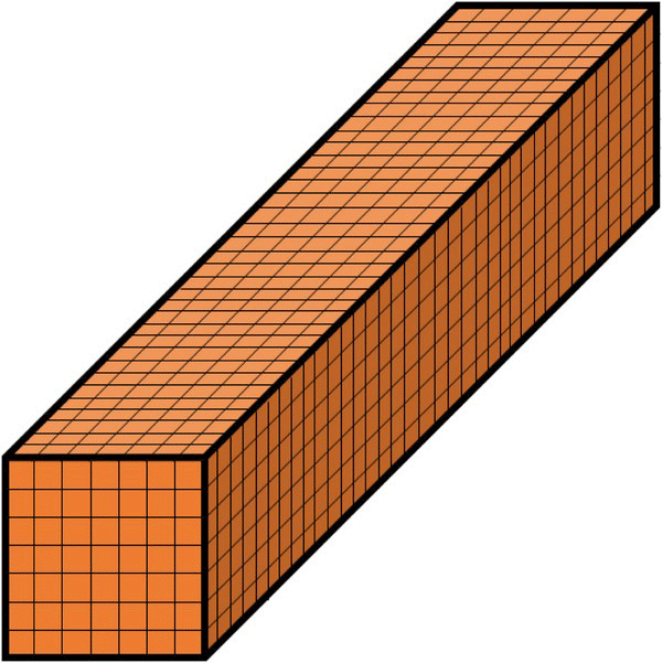
The wood to be subjected to moisture content prediction was 210 × 210 × 1800 mm red pine (Pinus densiflora) wood. When modeling the MC in wood, the number of nodes was width 8, thickness 8, and length 37. The simulation was performed with a total of 2368 nodes. In this study, the distance between the nodes was 30 mm in the x direction, 30 mm in the y direction, 50 mm in the z direction, and the time increment was 150 s.
In order to compare the theoretically predicted moisture content data with the actual values, 210 × 210 × 1800 mm red pine timber was dried according to the high temperature drying schedule shown in Table 2. The initial moisture content of the red pine wood was 45.25%. The predicted and actual internal moisture content distribution of the wood during the high temperature drying were compared by collecting the moisture content of the test specimens at the pre-determined times (Table 2). Both ends of the square timber were finished with paint to control the end check occurrence. Accordingly, the wood was took out from the dryer at 24, 72, 196, and 240 h, and the moisture content was measured in a sample taken at a distance of about 400 mm from the end of timber. The end of timber was then sealed with polyvinyl, and the wood was re-dried.
| Step | Time (hours) | Dry bulb temperature (°C) | Wet bulb temperature (°C) |
|---|---|---|---|
| 1 | 0~24 | 95 | 95 |
| 2 | 24~72 | 120 | 70 |
| 3 | 72~196 | 112 | 62 |
| 4 | 196~240 | 112 | 70 |
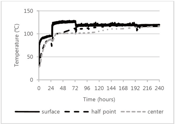
The temperature data used in estimating the moisture diffusion coefficient was obtained, by installing a K-type thermocouple during the actual operation. Four thermocouples were used, enabling measurement of the surface temperature of the wood, half-point temperature from the surface to the center, the center temperature, and air temperature between the woods.
3. RESULTS and DISCUSSION
During high temperature drying, the temperatures of red pine at half the point between the surface of the wood, the center, and the surface are shown in Fig 4. The air temperature between the woods was measured to be about 5 to 10°C higher than the target dry bulb temperature suggested by drying schedule. As a result of measuring the temperature of the center of the wood and temperature at the half point between the surface and the center, the temperatures inside the wood did not reach the dry bulb temperature until the end of drying, unlike the wood surface temperature. This result is because the heat of evaporation influences the heat transfer inside the wood, up to the later stage of high temperature drying. The temperature of the half point gradually increased after 24 h and remained almost the same as the surface temperatures after 196 h.
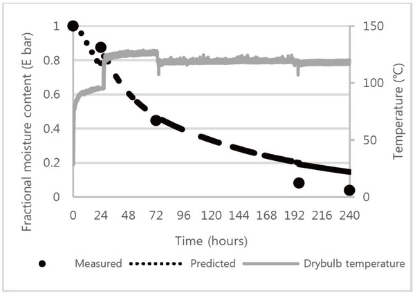
Based on the measured temperature and coefficients relevant to mass transfer, the moisture distribution in the wood was predicted. The moisture change according to drying time is expressed in Fig. 5, using the fractional moisture content (E bar, E = (AMC-EMC) / (IMC-EMC), where, IMC = initial moisture content (%); EMC = equilibrium moisture content (%); AMC = average moisture content (%)). Fractional moisture content is defined as the ratio of the average moisture content to initial moisture content.
The measured fractional moisture content at 24 h was higher than the predicted value, and the predicted 72 h result was similar to the measured value. However, the measured fractional moisture content at 196 and 240 h were lower than the predicted results.
Fig. 6 and Fig. 7 show the measured temperature profile, predicted and measured moisture distributions in longitudinal direction and transverse direction of red pine timber. Fig. 6(a) and Fig. 7(a) show temperature profile in longitudinal direction at each time. The temperature of each node was used to determine moisture diffusion coefficient and surface emission coefficient. Fig. 6(b) and Fig 7(b) show the predicted moisture distribution in longitudinal direction. The moisture content difference between the end part and the center part of the wood in longitudinal direction was not large. This is because the end coating was applied to the cross section of the wood.

Fig. 6(c) and 6(d) show the predicted and measured moisture distribution of the red pine timber at 72 h of drying, respectively. When the 72 h moisture content distributions were compared, the predicted results showed an average moisture content of about 13% and an actual average moisture content of about 10%, generating a 3% error. The simulation predicted that the moisture content gradient at each site would be comparatively gentle.
Fig. 7(c) and 7(d) display the predicted and measured moisture content distribution in the wood at 240 h of drying. After drying, the final moisture content was 7.22%, and the experimental result was 2.67%. The moisture content was very low, being less than 2% on the surface, but it was predicted that a high moisture content of 10% or more would still exist inside the wood because of the surface checking, as at 72 and 196 h of drying, several surface checks were observed. Drying checks might be occurred by great moisture content gradient formed in the wood dried through high temperature drying schedule suggested in this study. Consequently, surface checks occurred, and surface emission was also generated inside the wood, which rapidly decreased the total moisture of the wood. This results show that the prediction of moisture content profile in wood calculated by using the moisture diffusion coefficient and the surface emission coefficient is possible only for the wood without checking.

4. CONCLUSION
This study predicted the moisture movement in wood by the 3-D FDM during at high temperature drying. Based on the 3-D FDM, the moisture movement in the transverse and longitudinal direction of the wood was applied to the analysis of the moisture profile in the wood. The moisture diffusion coefficient was determined, by using the geometric moisture diffusion coefficient. The surface emission coefficient was calculated by considering the convective mass transfer coefficient. In order to compare the predicted results with the actual measurement results, we dried red pine timber at a high temperature and measured the average moisture content and the sectional moisture content of the wood at the time of the scheduled temperature change. Consequently, the prediction of the internal water movement of the wood up to 24 h, with a small wet bulb depression, showed a small error compared to the actual value, but thereafter, the actual fractional moisture content result was lower than the predicted result. This behavior is thought to be due to the checks on the surface of the wood. Therefore, the theoretical moisture diffusion coefficient and the surface emission coefficient used in this study are applicable for wood without checking.


