1. INTRODUCTION
The development of structurally engineered timber technology in Indonesia is relatively limited, although Indonesia has many wood species that can be utilized as raw materials in the engineered timber industry. Structurally engineered timber was engineered wood that functions as the main element in building construction, such as columns, beams, floor plates, shear walls, and roofs. Cross-laminated timber (CLT) is an engineered timber that offers the strength and stability required for its main structural elements. Globally, various timber species have been studied for their role in CLT production. Radiata pine timber produced CLT panels with bending and shear strengths exceeding the characteristic strength of the raw material (Li et al., 2020; Navaratnam et al., 2020). Southern pine, which is used as a raw material for CLT panels, produces bending and shear strengths that exceed V3 standards (Hindman and Bouldin, 2015). Hematabadi et al. (2020) observed bending and shear using poplar wood, and the results showed that the span-to-depth ratios were directly proportional to the moduli of rupture and elasticity in the major and minor strength directions. Crovella et al. (2019) conducted experiments using three types of wood: Eastern White Pine, Red Maple, and White Ash. The results showed that the bending stiffness, bending strength, and shear strength of hardwood were higher than those of softwood with the same lamina composition.
A hybrid CLT with outer layer hinoki (spruce, Chamaecyparis obtusa) and middle layer and sugi (Japanese cedar, Cryptomeria japonica) middle layer was conducted by Ukyo et al. (2021); the amount of rolling shear stress in the cross layer was 0.9–1.1 times the average shear stress, which was negatively correlated with the nominal shear strength. The use of hardwood improved the softwood characteristics of the hybrid CLT system in terms of both the bending stiffness and shear strength (Ma et al., 2021; Yang et al., 2021). Trisatya et al. (2023) recommended positioning high-density wood as the outer layer of hybrid CLT.
The tropical timber species investigated by Hariz et al. (2023) resulted in flexural mechanical properties of the puspa-acacia-puspa hybrid CLT equivalent to acacia CLT and had a shear strength that met the JAS 3079 standards. Galih et al. (2020) composited acacia with bamboo into a CLT material, and the results showed that the elastic modulus was 2.73 times higher than that of CLT using spruce pine fir (SPF) and the shear modulus was 0.8 lower than that of SPF CLT.
When using new wood species for the mass production of CLT, it is necessary to investigate the consistency of the theoretical models used to predict strength and stiffness (Crovella et al., 2019). Brandner et al. (2016) also emphasized that the consistency between the design and experimental methods used to predict the strength and stiffness must be proven accurately. However, the technical information on CLT based on tropical wood species from Indonesia is limited. Consistent theoretical models for predicting the strength and stiffness of CLT panels have not yet been developed; therefore, investigations on this matter are urgently needed.
Previous research on CLT has focused on the bending stiffness, bending strength, and shear strength of CLT with uniform lamina thickness. The diversity of lamina thicknesses in the CLT resulted in different stress distributions and affected the bending stiffness and shear resistance. This study aims to analyze the effects of different combinations of thickness and wood species on the mechanical performance of CLT to find more efficient and sustainable design solutions for modern construction applications. This study also provides an overview of the theoretical approaches that can be used to predict the stiffness and strength of CLT panels with different thickness configurations and lamina species.
2. MATERIALS and METHODS
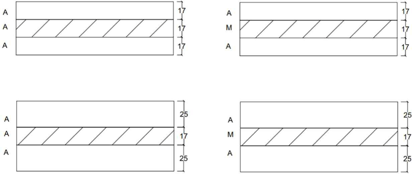
The materials used in this study were acacia and mindi species obtained from commercial wood suppliers in Indonesia. The specimens were categorized into two groups: one based on layer thickness and the other based on material composition, for example, acacia CLT and hybrid CLT. In the acacia CLT 3 (A-CLT/3) specimens, all layers used acacia timber with an average density of 0.622 g/cm3 (COV 0.07), whereas the hybrid CLT specimens (H-CLT/3) had longitudinal layers made of acacia and transverse layers made of mindi with an average density of 0.420 g/cm3 (COV 0.12). Based on the thickness of the layers, there were 3-layer CLT with a thickness of 17 mm for each layer and 3-layer CLT with a thickness of 25 mm for the longitudinal layer and 17 mm for the transverse layer (Fig. 1). The laminae used had a width of 100 mm and an average moisture content of 12%. Then the panels were conditioned for four weeks at 65 ± 5% RH. Polyurethane was used as the adhesive with a gluing spread of 160 g/m2. Pressing was performed using a hydraulic cold press for 1 h at a pressure of 1.20 N/mm2. From the preliminary tests referring to ASTM (2014), the modulus of elasticity (MOE) of acacia was obtained, with the tensile test yielding E0 = 14,832.16 MPa (COV = 0.14, n = 15) and the bending test providing E90 = 7,622.23 MPa (COV = 0.13, n = 15) and for mindi E0= 10,380.36 MPa (COV 0.13, n=10); E90= 3,461.08 MPa (COV 0.14, n = 10). The CLT were produced with dimensions of 1,200 × 2,400 mm and then cut according to the dimensions required of the type of testing performed.
The acacia CLT was subjected to a four-point bending test with a ASTM (2015) span-to-depth ratio (Rsd) of 1:25, and the loading configuration is illustrated in Fig. 2 and Table 1. The loads and deflections were recorded using a data logger. The global deflection (wglobal) was measured using longitudinal linear variable differential transformers (LVDTs) mounted at the midspan on both sides of the CLT panel. The panel was loaded constantly on the major axis at a displacement speed of 5 mm/min using an actuator equipped with a 100 kN load cell. The details of the CLT bending specimens are presented in Table 1.

The bending strength or modulus of rupture (MOR) of each specimen was calculated using the force equilibrium theory presented in Equation (1) and MOE in Equation (2).
Where Fmax is the ultimate load capacity, l is the span between the supports, l′ is the distance between the loading points, a is the distance between the support and loading point, F1 and F2 are 10% and 40% of Fmax, respectively, and w1 dan w2 the global displacements under the F1 and F2 conditions, respectively. G is the shear modulus, b is the width of the specimen, and h is the thickness. The global stiffness (EIG) of each specimen was calculated using Equation (3),
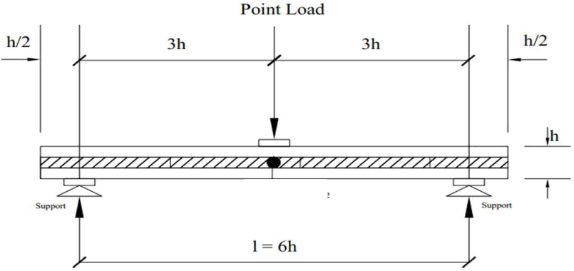
The determination of the shear properties of CLT 3 in this study was based on a ASTM (2015) short-span bending test with a span-to-depth ratio (Rsd) of 1:9, as shown in Fig. 3. The details of the specimen dimensions used in the shear tests are summarized in Table 2.
The shear stress of the CLT obtained from the bending test was calculated using Equation (4), where τr is the maximum shear stress (MPa), Fmax is the maximum load from the test, b is the panel width, and h is the thickness of the CLT panel.
The stiffness calculation approach (EI) for the CLT, which was assumed to be an isotropic material, was calculated using Equation (5) (Karacabeyli and Gagnon, 2019).
Where EIgross is the bending stiffness by gross cross section, E1 is the MOE of the outer layer, b and h are the width and thickness of the CLT specimen, respectively.
Unlike the isotropic approach, the Timoshenko beam theory is an extension of the Bernoulli–Euler beam theory used to calculate shear deformations in composite beams. It utilizes a shear form factor k to correct the cross-sectional shear stiffness and does not assume that the cross-section remains straight and perpendicular to the neutral axis (Ehrhart and Brandner, 2018; Rahman et al., 2020). The effective bending stiffness and shear stress of the laminated beams were calculated using Equations (6) and (7), respectively (Brandner et al., 2016; Wallner-Novak, 2014).
Another popular analytical approach is the Gamma method. The Gamma method describes the longitudinal layer as a beam and the transverse layer as a constantly distributed connection. It was assumed that the stiffness was loaded only on the transverse layer, which was identical to the rolling shear modulus (Huang et al., 2023b). In determining the contribution of shear deformation to deflection due to buckling, factor γi used to measure the efficiency of layer-to-layer interactions (Huang et al., 2023a). Subsequently, the effective bending stiffness and shear stress of the laminated beam were calculated using Equations (8) and (9), respectively (Ehrhart and Brandner, 2018):
Where
Other methods, such as shear analogy (SA), describe the layer panel as two systems composed of beam imaginers A and B (Christovasilis et al., 2016). The total inherent bending stiffness of the different layers was applied to Beam A along its neutral axis, whereas Beam B received the total shear stiffness of all layers, the neutral axis of the overall bending, and the combined bending stiffness of all layers and connections alone. Because the two beams were connected by a virtual beam composed of continuously dispersed link elements with unlimited axial rigidity, equal deformation at each point along the beam when carrying the transverse load had to be verified (Huang et al., 2023b). Subsequently, the effective bending stiffness and shear stress of the laminated beam were calculated using Equations (10) and (11) (Ehrhart and Brandner, 2018):
where
Where Ai is the cross-sectional area of each layer Ai = hi.b and Ei are the elastic moduli of each layer: Ei = E0 for the longitudinal layer and Ei = E90 = 0 for the transverse layers. I is the moment of inertia zi is the distance between the center of each layer and the center of the entire cross-section; V is the shear capacity obtained from short-span bending test; b is the width of the CLT panel; and ai distance between the center of each layer and the gravity center of the total cross-section; lreff is the reference span of the beam (Wallner-Novak, 2014). hi is the thickness of the layer in the direction transverse to the load (Karacabeyli and Gagnon, 2019). BA and BB denote the bending stiffness values.
3. RESULTS and DISCUSSION
The bending test results are listed in Table 3. Maximum load (Fmax); mid-span ultimate moment (Mmax); Δmax is the deflection at ultimate load taken from global measurements; and global MOE (Eg).
Table 3 provides an overview of the effects of adding thickness to the outermost layer or replacing the cross-layer wood species. All types of acacia CLT with three layers and hybrid CLT with three layers showed that increasing the layer thickness had a positive influence on the strength of the CLT panels. The mean MOE of A-CLT3/67 of 22,909.67 MPa with a COV of 13% is better than that of A-CLT3/51, whose mean MOE is 13,772.28 MPa with a COV of 4%, meaning that the addition of 8 mm to each outer layer can increase 39.88% of the MOE of the acacia CLT 3 layer. In the hybrid CLT type, the mean MOE of H-CLT3/67 is 17,106.88 MPa with a COV of 7% and H-CLT3/51 is 11,333.19 MPa with a COV of 23%, meaning that the panel in this type of CLT with a thickness of 67 mm has a 33.75% higher MOE value than the CLT panel with a thickness of 51 mm. It is generally known that engineered wood strength decreases as the wood size increases; however, acacia CLT and hybrid CLT show increased strength as the wood size increases. The increase in CLT thickness was not applied overall; instead, the thickness increased only in the outer layer. Owing to the out-of-plane bending, the stress is concentrated in the middle layer, allowing the strength to potentially increase despite an increase in thickness.
In the case of the cross-layer wood species, replacing the cross layer with a lower-quality timber species had a negative effect on the MOE value. The MOE of H-CLT3/67 was 25.32% lower than that of A-CLT/67 and H-CLT3/51 is 17.71% lower than that of A-CLT3/51. This study showed different failure modes in CLT panels according to the characteristics of each panel type. Fig. 4 illustrates the failure modes of the CLT-type composed of acacia, and Fig. 5 illustrates the failure mechanisms observed with respect to the different compositions of the middle layer made of mindi.
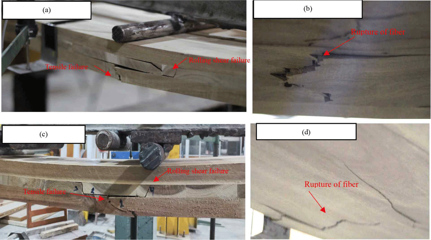

In A-CLT3/51 and A-CLT3/67, the most common failure was tensile failure at the bottom layer, with marked tearing of the timber fibers (Fig. 4). However, some samples were also subjected to rolling shear failure, which occurred after fiber tearing at the edge of the bottom layer of the CLT panel. The rolling shear was characterized by a z-pattern in the middle layer; this failure mode was likely due to the load distribution around the annual ring. Layer 3 failed in the form of fiber rupture because the load distribution acting on the tension area was fully carried by the outermost layer. This type did not experience true delamination failure; delamination occurred after tensile failure in the bottom layer and then propagated to the interface area of the bottom and middle layers.
The H-CLT3/51 and H-CLT3/67 samples showed similar failure patterns, namely, rolling shear failure in the middle layer following the annual ring pattern that propagated at the interface layer, resulting in delamination. This type of CLT did not experience tensile failure, because its ability to resist bending forces was not comparable to that of the longitudinal layer. In addition, polyurethane adhesive (PUR) tends to penetrate through the tracheids in softwood, which causes adhesive penetration into the mindi timber as the cross layer is less optimal, making the adhesive area more susceptible to delamination when subjected to bending loads (Kim et al., 2024b). Song and Kim (2023) suggested that the gluing of mixed timber CLT involving softwood requires a longer pressing time for deeper adhesive penetration and better delamination performance.
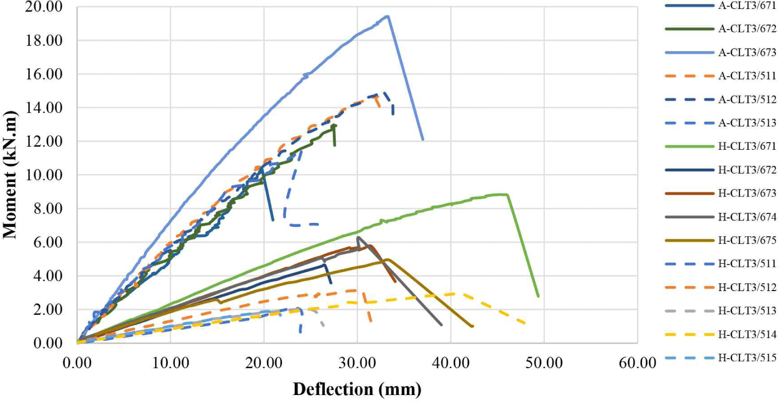
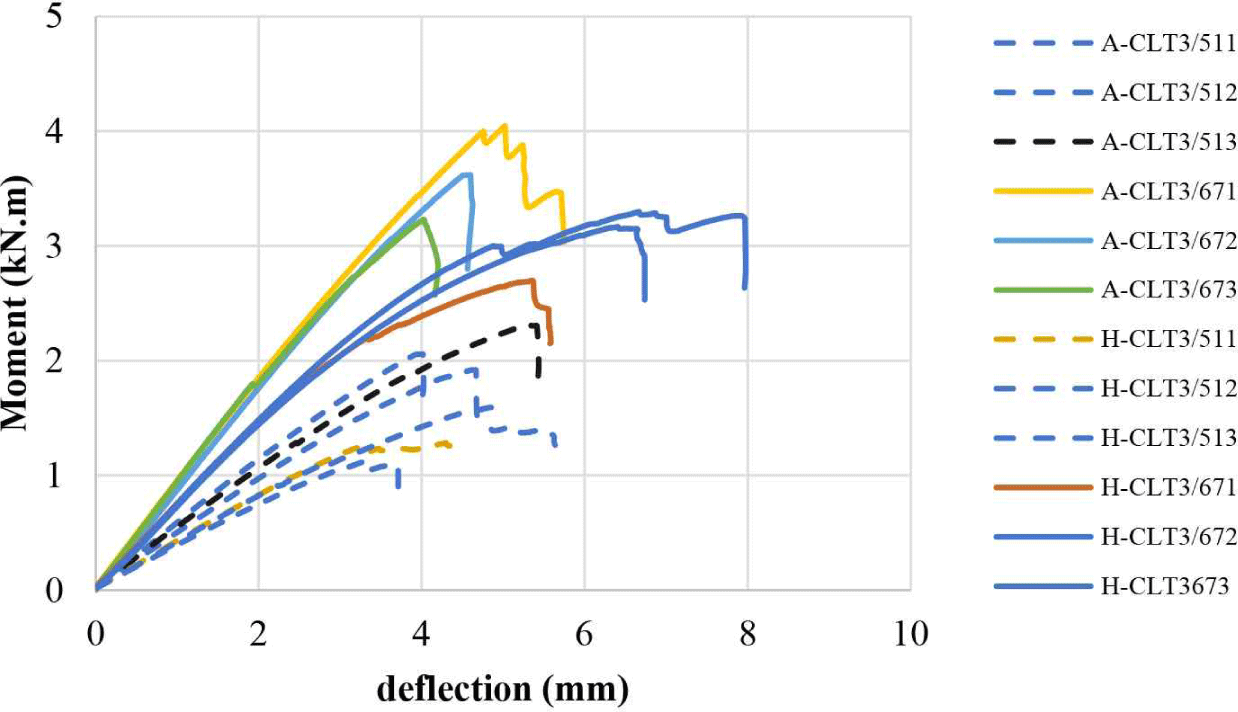
The moment-deflection correlation curves in Fig. 6 show the same pattern. The deflection was linear with the applied loading before reaching the maximum moment. A decrease occurred after the maximum moment was reached, and the CLT panel fractured. A-CLT3/51 reached an mean maximum moment of 10.46 kN.m with a COV of 14% while A-CLT3/67 reached a mean maximum moment of 15.06 kN.m with a COV of 33%. And in H-CLT3/51 and H-CLT3/67, the mean maximum moment were 2.41 kN.m (COV 25%) and 6.07 kN.m (COV 28%), respectively. From the moment versus deflection correlation curves, the initial stiffness of the acacia CLT was better than that of the hybrid CLT. This can be observed from the maximum deflection of the hybrid CLT being greater than that of the acacia CLT, and the degree of slope of the acacia CLT curve being greater than that of the hybrid CLT, as shown in Fig. 6.
The bending stiffness of the CLT sample was also calculated using the deflection measured during the test and then compared with the bending stiffness obtained using an analytical approach using several theories. A comparison between the test results and the theoretical calculations is presented in Table 4.
Based on the global stiffness calculation, it could be observed that A-CLT3/67 had an EI with an infinite shear modulus of 17.23E + 10 N.mm2 or 73.48% stiffer than A-CLT3/51 which had a mean bending stiffness value of 4.57E + 10 N.mm2. H-CLT3/67 obtained a mean EI with infinite shear modulus of 5.11E + 10 N.mm2 and H-CLT3/51 1.15E + 10 N.mm2, meaning that H-CLT3/67 had an EI value with an infinite shear modulus 70.45% higher than H-CLT3/51.
Sikora et al. (2016) reported that the thickness of a CLT panel was positively correlated with its stiffness. Overall, this study showed a uniform behavior in the correlation between the stiffness and panel thickness. However, in this study, the replacement of the cross layer with a lower-grade material reduced the stiffness by 66.95% %in CLT3/51 and 70.34% in CLT3/67.
The theoretical bending stiffnesses EIgross, EIgamma, EISA, EItimoshenko resulted in similar values. EIglobal was calculated using the deflection measured using the LVDT. Fig. 7 illustrated that EIglobal with infinite shear modulus (EI∞) showed lower values compared to EIglobal calculated using a shear modulus (G), G or shear modulus was obtained using the approach recommended by the wood handbook (Gedeon, 2010) which recommends that the value of G = 1/20 of the value of E0 for hardwood species. This means that the EIglobal with an infinite shear modulus was closer to the theoretical EI than the EI with a given shear modulus. This was similar to the study conducted in, He et al. (2018) in which the EI value with an infinite shear modulus had a smaller difference than the theoretical calculation.
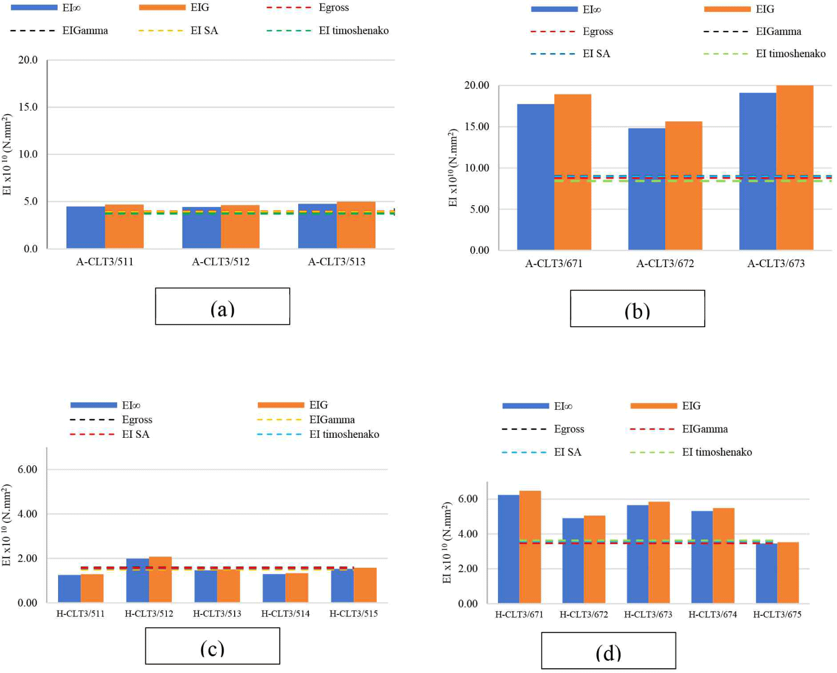
Fig. 7 and Table 4 illustrate the comparison of the EI test and prediction results, where the CLT panel type with a nonuniform layer thickness produced a much higher global EI than the EI predicted using several theories. It could be concluded that the characteristics of CLT composed of layers that have non-uniform thickness were different from CLT panels composed of layers with uniform thickness, from the equations offered in several theories had not been able to accommodate predictions on CLT panels with non-uniform layer thickness, especially using tropical hardwoods such as acacia timber and mindi timber as in this study.
The results of the shear tests are summarized in Table 5. Maximum load (Fmax); maximum shear capacity (Vmax); maximum mid-span moment (Mmax); and Δmax is the deflection at ultimate load taken from measurements.
The shear test results are shown in Table 5; a positive correlation was observed between the increase in layer thickness Vmax and MOR, with the increase being significant. A-CLT67 showed 33% higher Vmax than A-CLT51, whereas H-CLT67 produced 64% higher Vmax than H-CLT51. When compared with the composition of the constituent materials, the Vmax of A-CLT3/51 was 33% higher than that of H-CLT3/51, whereas that of A-CLT3/67 was 16% higher than that of H-CLT3/51. This meant that the thickness of layer and middle layer material affected the shear capacity, and MOR that can be carried by CLT panels. This result is in line with the report Li et al. (2021) that the shear capacity has a positive relationship with an increase in thickness; the thicker the CLT, the higher the shear capacity, and the shear strength of the CLT panel is influenced by the shear strength and fiber direction owing to the lamination of the transverse layer (Ma et al., 2021).
The moment and deflection correlation curve in Fig. 8 shows that at the same thickness of the CLT acacia panel, the linear area was longer than that of the hybrid CLT panel because each layer has the same characteristics, so that it holds the load more evenly and is more rigid than the hybrid CLT.
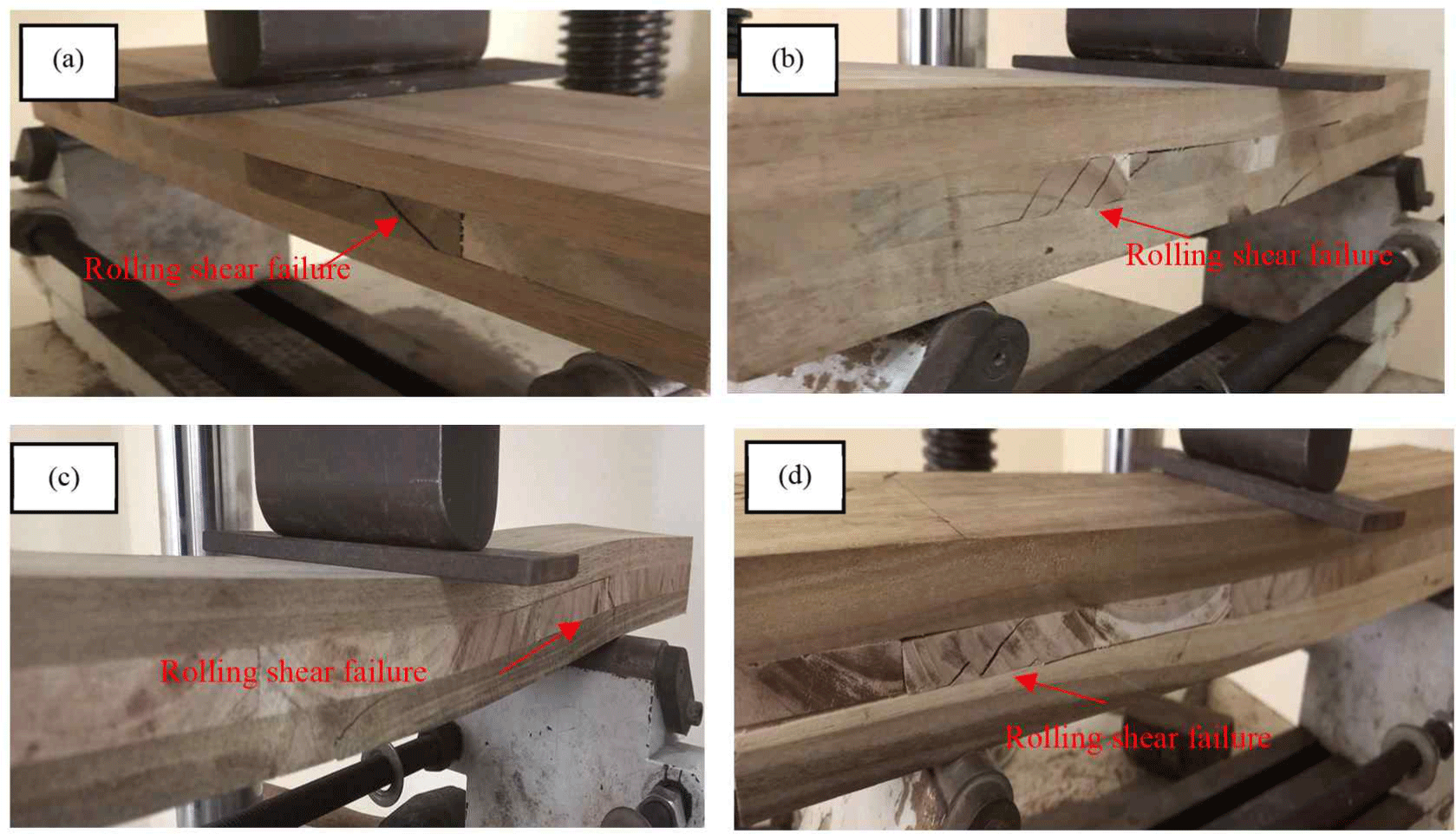
The failure modes of the CLT panels in the shear tests exhibited similar results. Acacia CLT exhibited an identical failure mode of rolling shear with a typical rolling shear failure mechanism in the middle layer. As shown in Fig. 9, the primary cracks in the transverse layer grew and spread along the annual ring orientation in the shear span before suddenly failing and dispersing in z- or multiple z-shaped patterns. The rolling shear failure pattern in the middle layer of the CLT is a common failure that occurs under high shear stress conditions (Kim et al., 2024a). Similar results were reported in Li (2017) an Li et al. (2021) examination of the CLT rolling shear strength characteristics of Radiata pine (Pinus radiata). Failure from the initial rolling shear close to the bond line was manifested as a shear stress transverse to the grain in the rolling shear behavior of the acacia CLT (Mohd Yusof et al., 2019). Notably, there was no evidence of adhesive failure (delamination) during the testing. The highest stiffness was observed in A-CLT3/67 panels, measured at 1.23E + 10 N.mm2 with a COV of 0.03 using infinite shear modulus G and 1.53E + 10 N.mm2 with a COV of 0.04 using shear modulus 1/20 E0. The increase in thickness was found to be directly proportional to the stiffness. As shown in Table 6, for the same thickness, the stiffness of H-CLT3/67 was 19% lower than that of A-CLT3/67. This indicated that the stiffness of the CLT panel was affected by the replacement of the middle layer. Shear strength (τr) test and analytical approach summarized in Table 6.
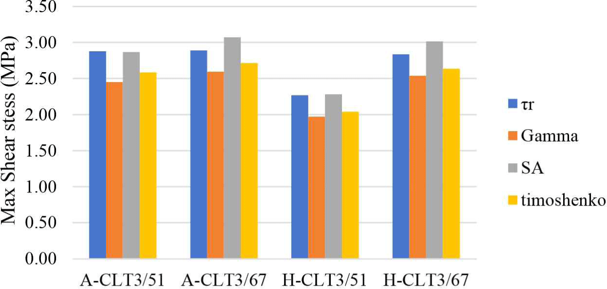
In terms of shear stress in each sample, the best shear stress was in sample A-CLT3/67 with a value of τr 2.89 MPa (COV 0.11), 0.01 MPa higher than that of A-CLT3/51. The addition of outer layer dimension did not significantly affect the shear stress (τr) in A-CLT3, the increase was around 0.34% and in H-CLT3 the increase is 19.71%. Modification of the cross section using mindi wood decreased the shear stress by 26.31% in the 51 mm thick CLT and by 1.76% in the 67 mm thick CLT.
This is not in line with, Sikora et al. (2016) who mentioned that increasing the thickness of the CLT decreases the shear stress. In this case, if the thickness is added only to the outer layer, the maximum shear stress does not decrease. The determining factor for the shear stress of the CLT panels was the performance of the middle layer; however, the (Yang et al., 2021) strength distribution in the thicker outer layer caused the shear stress to increase, although it was not significant.
The test shear stress was calculated using Equation (4) assuming an isotropic material. The shear stress was calculated using several equations: gamma theory, SA, and Timoshenako. The results are illustrated in Fig. 10, which shows that the approach using SA was more conservative in predicting the relevant shear stress on the CLT panels investigated in this study.
In this study, the thickness and bending stiffness had a positive correlation, meaning that the thicker the CLT panel, the greater the stiffness, which is in line with the research conducted by He et al. (2020) and Sikora et al. (2016). In this case, increasing the thickness of the outer layer with the load orientation on the major axis increased the bending stiffness of the CLT panel because the outer layer had the most significant influence on the bending strength of the CLT, was responsible for the bending load capacity, and tended to be zero in the middle layer (Hematabadi et al., 2021; Song and Kim, 2023). The replacement of the middle layer with a lower-quality material was recorded to reduce the bending stiffness of the CLT panel by more than 60% because the middle layer experienced shear failure before the failure of the outer layer. Therefore, the replacement of the middle layer with mindi in this case was deemed ineffective. The use of timber species of equal quality would have been more efficient in optimizing the performance of each layer according to its role.
In terms of the shear properties, the addition of an outer layer to all types of CLT resulted in a maximum shear stress increase of only 19%. This is because the outer layer, as the longitudinal layer of the CLT panel, experienced more residual stress from the middle layer, which caused a higher concentration of shear stress. Glasner et al. (2023) suggested that the thickness of the cross-layer is inversely proportional to the shear stress: the thicker the cross-layer, the smaller the shear stress, and the smaller the cross-layer thickness, the greater the shear stress. In fact, in this study, without changing the thickness of the cross layer, increasing the thickness of the outermost layer significantly increased the stiffness; an increase of 277% occurred in the CLT made of acacia wood, with an increase in shear stress of only 0.34%. A similar trend was observed for the hybrid CLT. Therefore, balancing the layer thickness to increase the stiffness without excessively increasing the shear stress is important in CLT panel designs.
4. CONCLUSIONS
Based on the investigations presented on the mechanical performance of CLTs made from acacia and acacia-mindi combined, it can be concluded that:
-
Acacia CLT had better stiffness than the hybrid CLT because, in acacia CLT panels, the lamina as a whole worked optimally according to the expected mechanism, whereas in the hybrid CLT, the lamina in the tensile and compressive areas did not work optimally in resisting stress due to major direction loading. The cross layer failed first in the form of a shear failure following the annual ring. Therefore, an equivalent timber must be selected so that the CLT panel can operate optimally.
-
An increase in the outer layer thickness effectively enhanced the stiffness by 277% in acacia CLT and 238.41% in hybrid CLT. Conversely, positioning mindi wood as the cross-layer in the hybrid CLT reduced the bending stiffness by 66.95% in the CLT with a thickness of 51 mm and by 70.34% in the CLT with a thickness of 67 mm.
-
The effect of the outer layer modification on the shear stress was not significant in acacia CLT, as it only decreased by 0.34%. In the hybrid CLT, the shear stress declined by 19.71%. Compared to each constituent material composition, a reduction of 26.31% occurred in the CLT with a thickness of 51 mm and 1.76% in the CLT with a thickness of 67 mm.
-
A theoretical SA approach can be used to predict the stiffness and shear stress of CLT panels composed of laminae of uniform thickness. For CLT panels with non-uniform lamina thickness, another mathematical approach is required to predict their performance more precisely.
