1. INTRODUCTION
Wood has been commonly used as a natural material to produce wooden structures, timber constructions, furniture, etc. from prehistoric times to the present day, undergoing processes such as logging, drying, joining, and assembly (Ghani and Lee, 2021; Hadi et al., 2022; Jamaludin et al., 2020; Kim and Kim, 2020; Ozdemir et al., 2023; Park et al., 2023). The processing traces remaining on wooden artifacts, hereafter referred to as tool traces, refer to the marks left by the processing tools at the time of artifact production and vary depending on the processing direction (Lim, 2011). The processing traces found on many archaeological artifacts can provide important clues for reconstructing the technological development process of ancient times with limited records, as they allow for the presumption of the tools used (Han, 2005). Additionally, based on woodworking culture, one can speculate the level of technological advancement at the time of production and verify social aspects such as the presence of skilled craftsmen and technological changes (Kim, 2010). However, despite its importance, research on wooden processing tools through tool-trace analysis is relatively scarce. Particularly, most studies have focused on small wooden objects, with little to no research on large-scale architectural timber components.
One of the major large-scale architectural structures, wooden storage facilities, refers to structures built in the form of boxes by assembling panels on the four sides, used for storing grains or goods. Among them, the dimensions of the wooden storage facility, known as wooden storage facility Class 3, are approximately 5 × 5 meters with a depth of about 2 meters (Park, 2022). These structures are mostly found in fortress towns or major administrative centers and are utilized as important resources for understanding the society of the time (Kwon, 2020). They are rarely found in typical village sites, and considering their relatively large scale and the requirement for abundant resources such as timber and labor, it is presumed that they were constructed not for private use but for public purposes in fortress towns or major administrative centers (Shin, 2005). Based on this presumption, it is suggested that wooden storage facilities represent a culmination of the timber processing technology of the time.
Tool traces can vary in appearance depending on factors such as the type of wood being processed, cutting tools used, and cutting conditions. The characteristics of cutting stock can vary depending on factors such as the type of wood being processed, its specific gravity, moisture content, temperature, grain orientation, and the presence of defects like knots. Additionally, the shape and size of the cutting tools, the angle of the blade, the material of the cutting tool, and pre-treatment processes can all contribute to different forms of tool traces. Cutting conditions include factors like cutting speed (rotation speed and feed rate), chip thickness and width, and cutting directions (Jeong, 1994). However, most of the previous studies on tool traces have focused on experiments using softwood lumber, making it difficult to apply the findings to the analysis of tool traces on large-scale architectural components made from hardwood species such as oak (Quercus spp.) during the Baekje period. Moreover, a previous study examined the production process of small wooden objects (Gaya National Research Institute of Cultural Heritage, 2020), making it challenging to assume the processing technology of large architectural components based on solely on such findings.
Therefore, in this study, we aimed to investigated the primary wood species used in the construction of wooden storage facilities excavated from the Baekje Sabi period (538–660 AD) in Chungcheongnam-do province, including the Bongseon-ri site in Seocheon, the Seongeosan Mountain Wirye Fortress site in Cheonan, Baekryung Fortress site in Geumsan. Based on the survey results, we attempted to replicate the tool traces remaining on the wooden storage facilities using oak, the primary wood species, and compared them with the actual tool traces found on excavated artifacts for cross-validation.
Previous studies on tool traces have predominantly utilized methods such as visual observation, optical microscopy, and scanning electron microscopy (Han, 2005; Park, 2022). Through these previous studies, it was noted that some of the tool trace analyses were conducted using destructive methods involving sample collection. Therefore, in this study, we employed non-destructive methods such as 3D scanning to objectively record the length and shape of tool traces for analysis. For microscopic analysis of the fine traces that are difficult to observe in 3D scan data or photographs, we utilized optical microscopy.
2. MATERIALS and METHODS
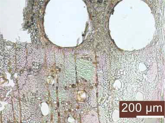
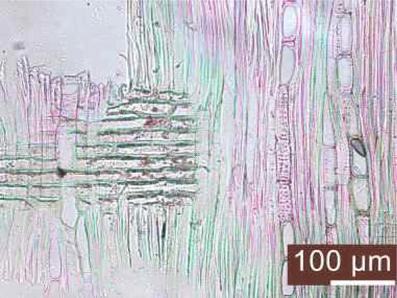
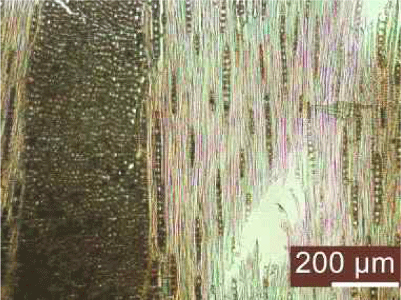
The cutting stock was obtained from forests located in Buyeo-gun, Chungcheongnam-do, with a diameter of 40 cm and a length of 400 cm. The wood species belonged to the genus Quercus, with a green density of 0.82 and an oven-dry density of 0.80 (Forestry Research Institute, 1994). The average oven-dry moisture content was measured to be 56.3%. To accurately investigate the wood species, species identification was conducted using the and section method, and the results are presented in Table 1.
| Cross section (× 100) | Radial section (× 200) | Tangential section (× 100) |
|---|---|---|
|
|
|
The wood was classified as ring-porous wood, belonging to the hardwood category, with pore zones isolated in 1–2 rows. Vessels were arranged radially with circular perforation plates. Longitudinal parenchyma cells were arranged in diffuse or short tangential bands, and the medullary rays were homogeneous. Broad rays and compound rays were observed together, confirming the presence of compound rays. Based on the observation that the vessels have circular to oval perforation plates and the presence of ring-porous characteristics within the genus Lepidobalanus, the wood was identified as the Lepidobalanus genus, commonly known as oak. While both Quercus acutissima and Quercus variabilis exist within the Lepidobalanus genus, it was challenging to distinguish them anatomically, so they were identified as Lepidobalanus species (Park et al., 2022).
Species identification was carried out with reference to “Wood Anatomy and Identification” (Park et al., 1987), “Structure of Korean Wood I” (Lee, 1997a), and “Structure of Korean Wood II” (Choi et al., 2022; Lee, 1997b).
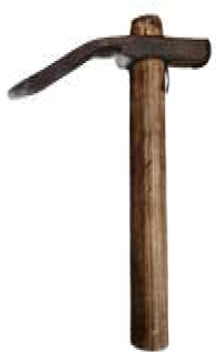
On the surface of the timber components, particularly the planks, of the wooden storage facilities, numerous distinct adze traces, measuring approximately 50–60 mm, were observed. Some areas showed traces of sawing, but due to the inability to clearly determine the endpoints of these saw traces, their lengths could not be precisely determined. On the support beams, grooves of approximately 100 mm were visible, presumably made by an adze for accommodating tenons. In some cases, traces resembling chisel traces, measuring approximately 25–35 mm, were observed in the mortise holes of certain support beams (Table 2). Based on these observed tool traces and their dimensions, we reproduced the manufacturing process of the Baekje-period wooden storage facilities using similar-sized saw, adzes, and chisels, and observed the tool traces (Table 3). The detailed classification of tool traces was based on previously published academic papers, categorizing them into blade-top traces, blade traces, and plucked traces on the cutting surface. Blade-top traces are marks left when the tip of the blade penetrates into the wood, forming independent traces that provide information about the width of the blade without interference from adjacent cutting surfaces. Blade traces are marks left as the blade passes over the wood surface, while plucked traces occur as wood fibers detach from the surrounding area near the blade-top trace (Han, 2005).
| NO. | Subject | Picture |
|---|---|---|
| A | Adze-trace and chisel-trace |
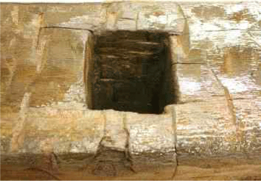
|
| B | Saw-trace |
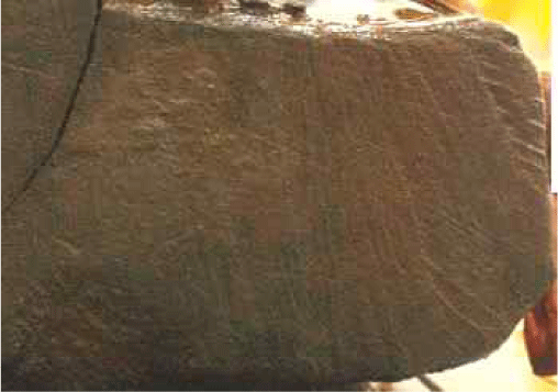
|
| C | Adze-trace |
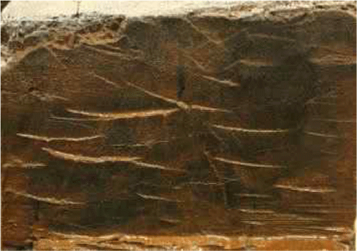
|
| D | Chisel-trace |
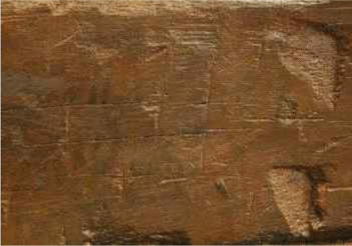
|
| Adze (60 mm) | Chisel (35 mm) | Saw (350 mm) |
|---|---|---|
|

|

|
The tool traces remaining on the components of the Baekje period wooden storage facilities, classified by type, were reproduced using adzes, chisels, and saws. The production process of the Baekje period wooden storage facility components for replicating tool traces was conducted as follows.
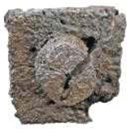
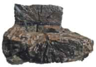
The components of the wooden storage facilities were classified by shape, and the cutting targets were selected accordingly (Table 4), Tenons were shaped individually and processed into a cylindrical shape at the bottom to complete them. Planks were dimensioned into plank forms based on previous research (Park, 2022), and mortises were created at the midsection of the planks to replicate the observed chisel traces. Furthermore, circular mortises were carved into the halving joint areas to allow for the observation of tool traces on the support beam components.
| Name | Shape of components | Cross section of components |
|---|---|---|
| Wall |

|

|
| Floor |

|

|
| Tenon |

|
|
| Strut |

|
|
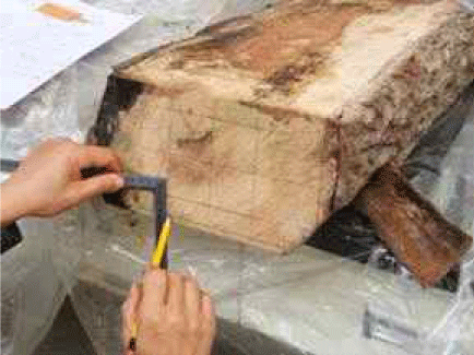
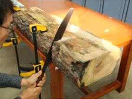
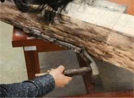
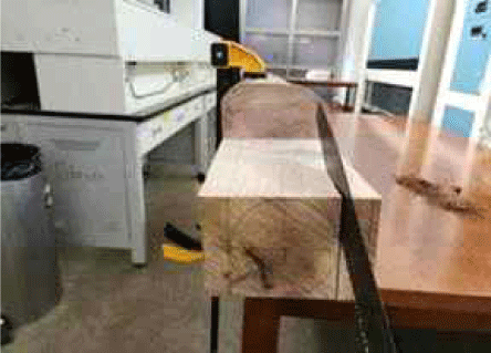
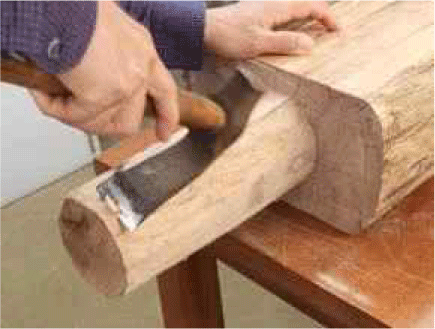
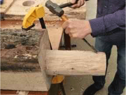
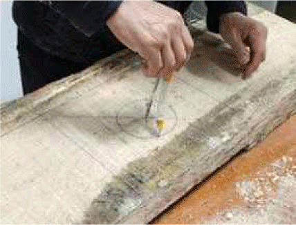
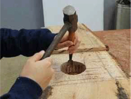
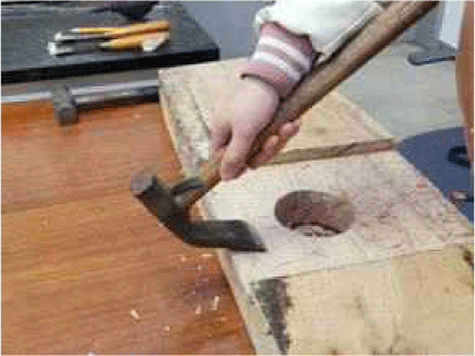
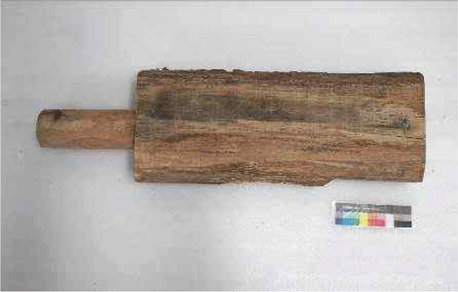
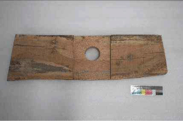
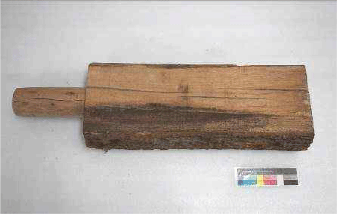
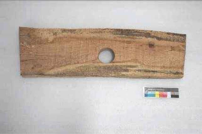
The production process is as follows. After harvesting the oak logs, it was difficult to shape all sides using an adze due to the log’s cylindrical form. Therefore, the logs were dimensioned into a predetermined shape using machinery. For tenon processing, outlines were drawn on the wood, and then the wood was cut and shaped using a saw and adze. Considering that the appearance of tool traces may vary depending on the skill level of the craftsman, individuals less familiar with adze usage and experienced craftsmen proficient in woodworking with adzes were assigned to process different sections of the surfaces. After processing the surfaces, cylindrical tenons with a diameter of approximately 95 mm and a length of approximately 250 mm were crafted using chisels and adzes (Table 5). For plank-shaped components, after drawing outlines for mortise holes, holes were drilled using chisels and then refined. Additionally, to ensure that the tenons fit securely into the mortise holes, half-lap joints with a height of approximately 20 mm were chiseled to completion (Table 6). The completed components, including tenons and mortise holes on plank-shaped components, are illustrated in Table 7.
| NO. | Picture | NO. | Picture | NO. | Picture |
|---|---|---|---|---|---|
| (a) |
|
(b) |
|
(c) |
|
| (d) |
|
(e) |
|
(f) |
|
| NO. | Picture | NO. | Picture | NO. | Picture |
|---|---|---|---|---|---|
| (a) |
|
(b) |
|
(c) |
|
| Appearance | Tenon | Plank with mortise |
|---|---|---|
| Front |
|
|
| Rear |
|
|
To objectively measure the length and shape of the tool traces formed during the reproduction process, a 3D scan was conducted. The 3D scan was performed using a handheld VCSEL scanner (Artec Leo, Artec 3D, Senningerberg, Luxembourg), which utilizes high-precision and high-accuracy non-contact active scanning, from a close distance (within approximately 2.5 meters). During the 3D scan, the precision was adjusted to ensure that the tool traces on the components were adequately captured, with HD data recording mor than 1/4 and texture exposure time exceeding 200 microseconds. The 3D scan data of the components were edited and finalized using the Artec Studio 17 Professional software.
Fine tool traces that were difficult to observe with the naked eye or 3D scan data were examined using optical microscopy. A portable digital microscope (Dino-Lite plus, AM313, New Taipei City, Taiwan) was utilized, considering the size of the components. The focus and magnification were adjusted to ensure clear observation of the tool traces, and images were captured accordingly.
3. RESULTS and DISCUSSION
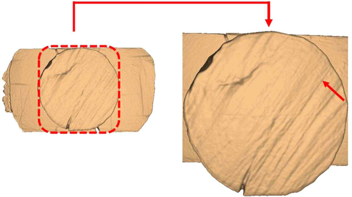
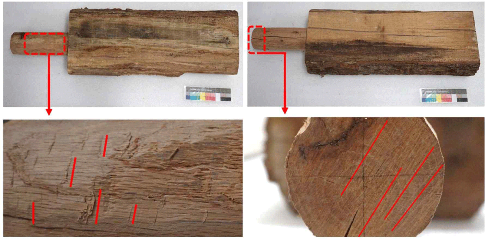
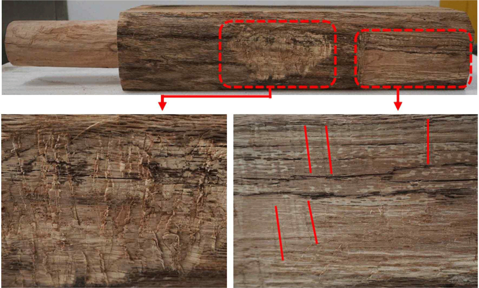
On the overall surface of the tenon components, adze traces and plucked traces, approximately 60 mm in length, were observed. Additionally, diagonal continuous saw traces, resulting from the sawing motion, were observed on the transverse section of the tenon, along with indentations of approximately 35 mm caused by chisels during the process of shaping the tenon into a cylindrical form (Fig. 1). When classifying these tool traces according to the skill level of the craftsmen, noticeable differences were observed between the adze traces of novices and those of skilled craftsmen. Novices’ adze traces appeared less uniform, with numerous plucked traces observed overall, while skilled craftsmen’s surfaces appeared smoother, with only a few adze traces remaining (Fig. 2).
Upon comparing these reproduced tool traces with actual artifact photographs (Table 2), it was noted that although the residual patterns were similar, the tool traces on the actual artifacts appeared more distinct. Two possible reasons for this discrepancy were considered. Firstly, differences in the weight and the radius of rotation of the tools could have contributed. While handheld adzes were used in the reproduction process, it is possible that during the actual artifact production, heavier adze blades or the use of longer handles for two-handed operation might have resulted in deeper tool traces on the wooden surface. Secondly, differences in post-processing after the fabrication process could also have played a role. While meticulous processing was conducted overall in the reproduction process, it is conceivable that in the case of actual artifacts, where the fit of the half-lap joints and mortise holes did not perfectly align with the mating components, additional processing might have been carried out to achieve alignment, potentially resulting in less precise tool traces.
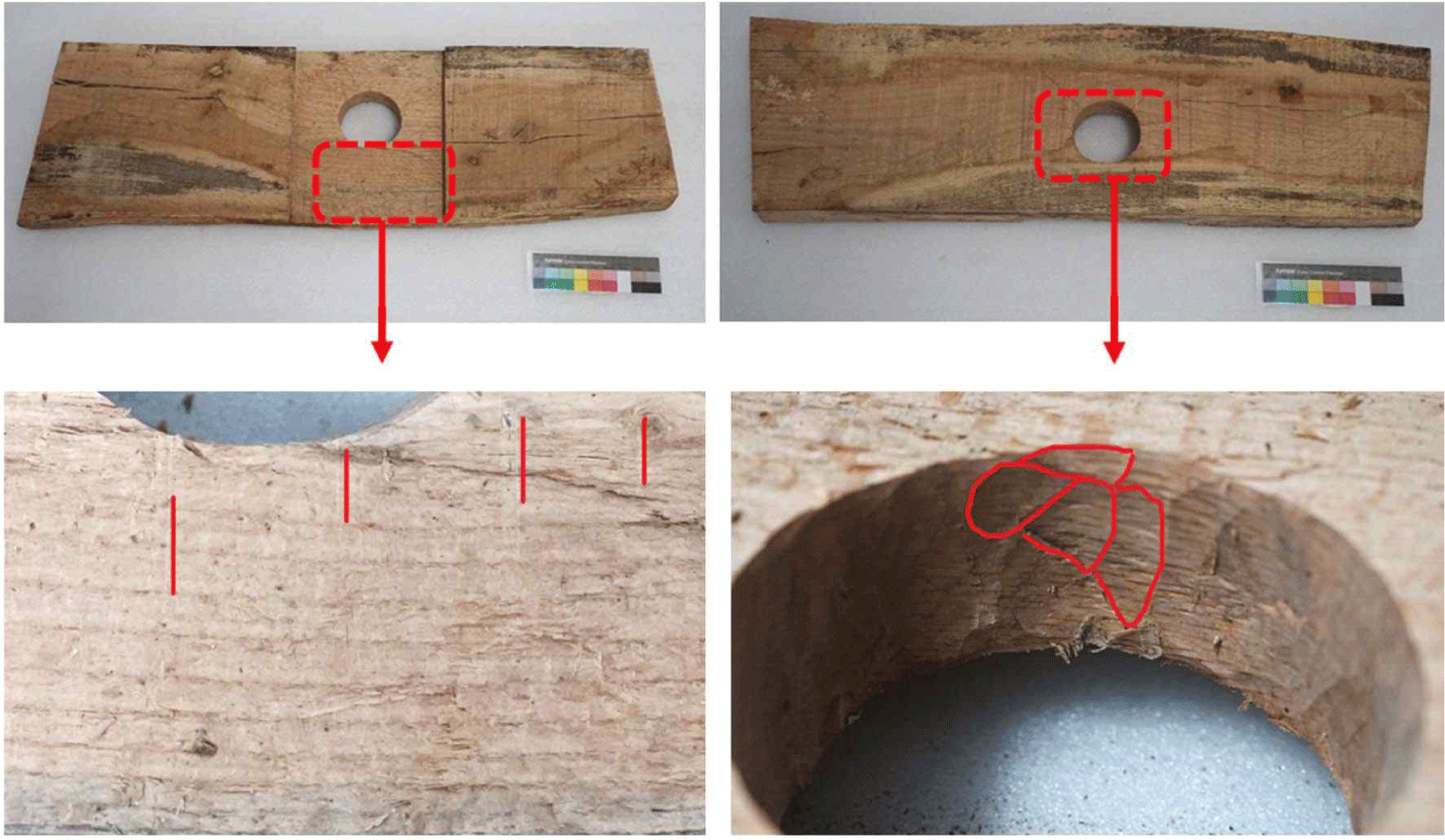
On the half-lap joints of the plank components, subtle adze blade traces, approximately 60 mm in length, were observed. In contrast to the tenon components, there were fewer plucked traces from adze blades on the plank components, making adze-trace observation challenging overall. This difference is attributed to the fact that while adzes were commonly used for cutting purposes during the fabrication of tenon components, they were primarily utilized for flattening the surface of the plank components. Additionally, continuous chisel blade traces were observed in the mortise holes (Fig. 3).
Upon comparing these results with actual artifact photographs, similar to the tenon components, it was observed that the tool traces on the actual artifacts appeared more distinct. This was interpreted as being due to differences in the tools used and variations in the completeness of the fabrication process, as was the case with the tenon components.
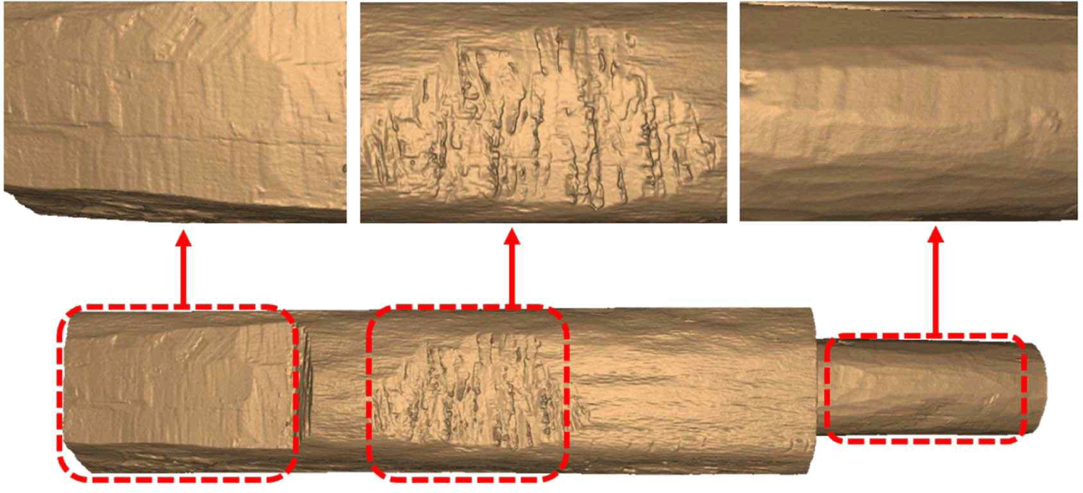
In the 3D scan results of the tenon components, observations of adze traces revealed significant differences between novice and skilled craftsmanship. Novice adze traces exhibited numerous plucked traces and some delamination of surrounding wood fibers. In contrast, skilled adze traces showed smooth blade traces of approximately 60 mm in length, accompanied by continuous chisel blade traces, without any noticeable delamination of wood fibers. This suggests that utilizing 3D scanning allows for clearer observations of continuous chisel blade traces compared to photographic methods. Additionally, chisel traces, which were challenging to capture accurately due to variations in lighting and angles in photographs, could be accurately recorded through 3D scanning (Fig 4). Finally, saw traces appeared as continuous surface scratches, enabling approximate determination of the saw’s cutting direction (Fig. 5)
The 3D scan results of the plank components revealed similarities in overall surface machining results compared to the tenon components. However, differences were observed in the areas where chisels were used. Ion the tenon components, faint blade traces of approximately 35 mm and continuous chisel blade traces were visible. In contrast, blade traces were challenging to observe in the plank components, and the chisel blade traces appeared relatively broader compared to those in the tenon components (Fig. 6). This difference is attributed to the restricted range of motion and tool usage when machining the mortise holes in the plank components, as opposed to the freer rotation radius in the tenon components.

Microscopic examination of adze and chisel blade traces on both tenon and plank components revealed interesting findings. Adze blade traces exhibited approximately 60 mm of fiber breakage traces. Similar to the 3D scan results, adze blade traces were found to vary depending on the impact angle and the skill level of the craftsman, sometimes forming plucked traces and sometimes leaving only blade traces [Fig. 7(a) and (b)].
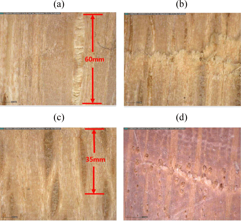
On the other hand, chisel blade traces showed approximately 35 mm of faint blade traces. When compared to adze blade traces, chisel blade traces exhibited a similar pattern even under microscopic examination [Fig. 7(c) and (d)]. Therefore, distinguishing between adze and chisel blade traces based solely on their appearance might be challenging. However, considering the width of the blade, it is possible to differentiate between them based on the length of the blade traces. Additionally, like the 3D scan results, it was observed that there were variations in the residual traces depending on the direction of chisel movement (parallel or perpendicular to the wood fibers). This study found that estimating the blade width of the woodworking tools used during production is possible through the analysis of residual blade traces on the components.
4. CONCLUSIONS
Based on the findings, this study has the following conclusions.
-
The surface finish of wooden tools varied significantly depending on the skill level of the craftsman, and significant differences in residual traces were observed depending on the degree and direction of processing. In the case of novice woodworkers, numerous traces of scraping were observed in addition to surface marks from the blade. In contrast, for skilled craftsmen, apart from blade marks visible to the naked eye, processing marks were hardly observed on the surface, and it was confirmed that the processing was carried out to a flat enough extent that traces could only be found through 3D scans and real microscope observations. When comparing the tool traces between reproduction artifacts and actual artifacts, it was found that the tool traces remaining on the actual artifacts were more distinct. This suggests differences in the weight or rotation radius of processing tools used during the construction of wooden architecture at that time, indicating that meticulous processing was not carried out during the production process at that time.
-
Chisel traces showed varying results depending on the direction of chiseling. When chiseled in the direction of the grain, shallow blade traces in a straight form continuously remained, whereas when chiseled perpendicular to the grain, distinct scraping marks remained. Chisel blade-top traces closely resembled adze blade-top traces, making it possible to distinguish them through the width of the blade.
-
Saw traces appeared as multiple layers of straight lines, allowing for the inference of the approximate cutting direction. However, due to the overlapping nature of saw cuts, it was difficult to determine endpoints, posing challenges in estimating the length of saw blades.
-
Among the methods for tool trace research, scanning electron microscopy (SEM) imaging has the advantage of being able to closely observe cellular cutting patterns despite the possibility of some sample destruction. While 3D scanning used in this study allows for non-destructive investigation of processing marks on wooden cultural heritage, it has limitations in observing cellular-level details. Therefore, it is considered important for future tool trace research to carefully select appropriate research methods based on the condition of cultural heritage.
Based on the above results, it is expected that a foundation of data regarding ancient large-scale wooden architecture’s carpentry techniques and wood processing tools can be established and utilized. The analysis of tool traces on future excavated wooden cultural heritage sites could serve as reference material.

