1. INTRODUCTION
Three-dimensional (3D) printing technology, also known as additive manufacturing, is being actively researched in various fields such as construction, aerospace, automobile, medical, and tissue engineering (Bae and Kim, 2021; Dickson et al., 2020; Ngo et al., 2018; Rahmatabadi et al., 2023a; Shin et al., 2018). Unlike the conventional molding process requiring individual molds to produce objects, 3D printing is regarded as a very promising technology because 3D models can be operated using a computer control software to produce complex and high-resolution objects without special tools (Rahmatabadi et al., 2023b; Xu et al., 2018). Among the various 3D printing technologies, fused filament fabrication (FFF) creates a 3D shape by depositing individual layers after melting an extruded thermoplastic polymer-based filament using a heated nozzle (Bae et al., 2021; Chacón et al., 2017; Rahmatabadi et al., 2023b). The common filaments used in FFF 3D printing are thermoplastic polymers such as polylactic acid (PLA), acrylonitrile butadiene styrene, poly(ε-caprolactone), and polyhydroxyalkanoate (Vatani et al., 2015). Among the thermoplastics, PLA is currently the most utilized material in FFF 3D printing as a biodegradable polymer typically derived from renewable resources (corn starch, tapioca roots, sugar cane, sugar beet, etc.; Jamshidian et al., 2010). PLA is very suitable to be used as a filament for FFF 3D printing because it offers the advantages of good stiffness, easy processing, and biocompatibility (Liu and Zhang, 2011). However, the use of PLA as FFF 3D printing filament has limitations due to disadvantages such as low thermal stability, relatively high cost, and low biodegradability (Wang et al., 2017). To overcome these shortcomings, various approaches are being attempted to study PLA-based biocomposites reinforced with natural fibers (Lee et al., 2021).
Cellulose fiber is the most abundant natural resource on earth. It offers the advantages of renewability, low density, biodegradability, low energy consumption, and low cost (Frone et al., 2011; Lu and Drzal, 2010). Cellulose fibers are usually long fibers and can take a variety of sizes and shapes. Among the cellulose fibers, micro-sized cellulose fiber (MCF) shows improved properties in various applications including composites (Moon et al., 2011). MCF also has a high aspect ratio because its diameter is in the micrometer range, which can provide improved mechanical properties to composites (Kim et al., 2019). However, MCF is hydrophilic in nature; thus, it has a disadvantage of poor compatibility when applied as a filler to a hydrophobic polymer matrix. Additionally, small-sized MCF fillers have much higher surface activities than other bigger cellulose fiber types, resulting in very strong aggregations between the hydroxyl groups of MCFs (Lu et al., 2008). This property indicates poor interfacial adhesion with the polymer matrix, resulting in deteriorated mechanical and thermal properties. Therefore, additional treatments are required to apply the MCF as a filler to the PLA matrix.
Studies have been conducted to increase interfacial compatibility by reducing the hydrophilic functional groups of cellulose fibers. As typical chemical modifiers, maleic anhydride (Lai et al., 2003), isocyanates (George et al., 2001), acetic anhydrides (Pawar et al., 2013), titanates (Bose and Mahanwar, 2006), and silanes (Jain et al., 2022; Xie et al., 2010) have been used. In particular, surface modification using a silane coupling agent is induced on the surface of the original fiber without damaging the cellulose fiber. Additionally, it has been reported that the degree of substitution from hydroxyl group to silanol group can be controlled by adjusting the content of the silane coupling agent (Xie et al., 2010). Therefore, surface modification using silane treatment on the MCF surface is proposed as an efficient method to improve the interfacial compatibility between MCF and PLA. However, little research has been done on FFF 3D printing filaments using surface modification by silane treatment.
In this study, PLA was filled with MCF because MCF is an abundant, sustainable, renewable, and biodegradable micrometer-sized reinforcing natural filler, which is expected to be well suitable for FFF 3D printing processes that deposit extruded layers through a very small diameter nozzle. However, MCF fillers without additional treat-ment have relatively low compatibility with the PLA matrix, resulting in aggregations. The aggregated MCF fillers can lead to not only nozzle clogging but also poor dispersions of MCF in the PLA matrix. To address these issues, silane treatment was introduced prior to melt compounding to reduce the number of hydroxyl groups on the MCF surface. Afterwards, various MCF/PLA blends were commingled to manufacture filaments for FFF 3D printing and then composite specimens were fabricated using a FFF 3D printer. The aim of this study is to investigate the effects of silane coupling agent on the optical, morphological, mechanical, and thermal properties of the 3D-printed MCF/PLA composites.
2. MATERIALS and METHODS
PLA (IngeoTM Biopolymer 4032D) with a melting temperature of 155°C–170°C, melt flow index of 7 g/10 min (210°C/2.16 kg), and density of 1.24 g/cm3 was purchased from NatureWorks LLC (Blair, NE, USA). MCF (Fibra-Cel® BH-40) in the form of a fine powder with wet density of 216 g/L, average fiber length of 65 μm, and ash content of less than 0.3% was provided by Celite (Santa Barbara, CA, USA). 3-aminopropyltriethoxysilane (APTES, XIAMETERTM OFS-6011), was obtained from Dow Corning (Midland, MI, USA). As reagents used for the silane treatment, ethanol with a purity of 99.5% and glacial acetic acid with a purity of 99.7% were purchased from Daejung Chemicals & Metals (Siheung, Korea). All reagents were used without additional purification.
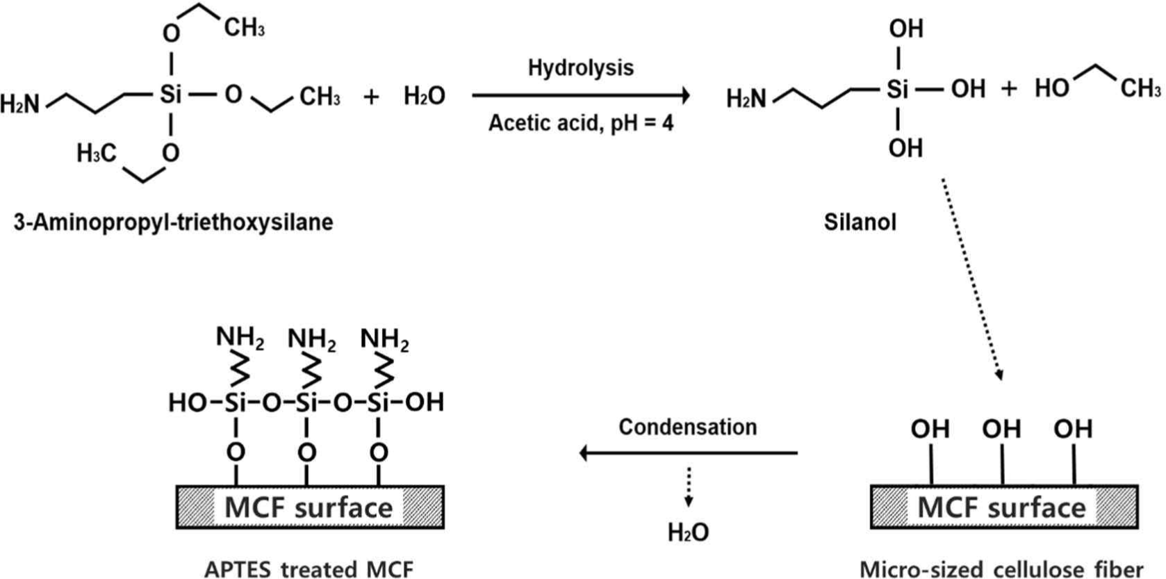
Before silane treatment, the MCF powder was dried at 80°C for 24 h. For the silane treatment, the ratio of ethanol and distilled water was 8:2, and, the APTES concentration was set to 3 wt.% (based on the weight of MCF). For APTES hydrolysis and stabilization of the silanol groups formed in the solution, the solution pH was adjusted from 4.0 to 4.5 using appropriate addition of glacial acetic acid. APTES was hydrolyzed by stirring in the solution for 1 h at room temperature. Then, the MCF powder was added into the solution and the silane treatment of MCF was conducted by stirring for 2 h at room temperature. The silane-treated MCF immersed in the solution was washed at least three times using ethanol and distilled water. The silane-treated MCF was vacuum-filtered and then the filtered silane-treated MCF was dried at 80°C for 24 h to remove the remaining moisture. The overall procedure for the silane treatment of MCF is shown in Fig. 1.

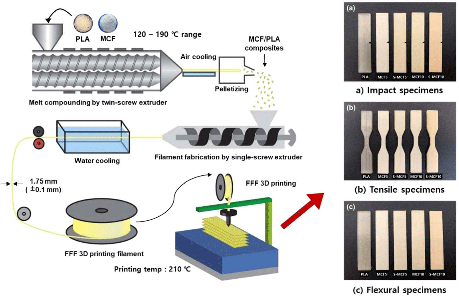
PLA was dried at 55°C for 48 h before compounding. PLA and the untreated or silane-treated MCF were melt-compounded using a BA-19 co-rotating twin screw extruder (Bautek, Pocheon, Korea) with a length-to-diameter ratio of 40 and eight temperature zones. The barrel temperature zones were set to 180°C, 185°C, 190°C, 185°C, 180°C, 175°C, 170°C, and 120°C, and the extruder rotation speed was 65–70 rpm. The formulation ratios for the various MCF/PLA blends are shown in Table 1. The extruded blends were pelletized using a BA-PLT pelletizer (Bautek) after air cooling.
| Specimen | PLA | MCF | Silane-treated MCF |
|---|---|---|---|
| (wt.%) | |||
| PLA | 100 | - | - |
| MCF5 | 95 | 5 | - |
| S-MCF5 | 95 | - | 5 |
| MCF10 | 90 | 10 | - |
| S-MCF10 | 90 | - | 10 |
The filaments for 3D printing applications were prepared using a single screw extruder (Doldam, Gumi, Korea) with previously extruded pellets. The extrusion temperatures were set to 200°C and 210°C. The extruded filaments had the diameters of 1.65–1.85 mm after cooling in a water bath.
The WEG3D X1 FFF 3D printer (Hepzhibah, Incheon, Korea) with a nozzle diameter of 0.6 mm was used. Slicing of the 3D models for the FFF 3D printing was conducted using an Ultimaker Cura software, which was converted into g-code files. The g-code files were loaded by the WEG3D 3D printer software and then 3D-printed to prepare the specimens for the impact, tensile, and flexural tests. The temperatures of the nozzle and heating plate were set to 210°C and 60°C, respectively. The infill density, infill printing speed, printing angle (i.e., raster angle), and layer height of the 3D-printed specimens were set to 100%, 40 mm/s, 0°, and 0.2 mm, respectively. The overall procedure for the 3D-printed specimen preparation by FFF 3D printing is shown in Fig. 2.
Fourier transform infrared (FTIR) spectroscopy was used to analyze the changes in chemical composition of MCF surface by silane treatment. The Frontier FTIR spectrometer (PerkinElmer, Waltham, MA, USA) was performed with a scanning wavelength from 4,000–400 cm–1 (32 scans).
The morphologies of the 3D-printed MCF/PLA composites were characterized using a JSM-7401F (Jeol, Tokyo, Japan) field emission scanning electron microscope (FE-SEM). After the Izod impact test, the fractured surface of the specimen was observed. The fractured surface was platinum-coated, and then analyzed at an acceleration voltage of 10 kV.
Izod impact strength tests were performed using a DTI-602B digital impact tester (Daekyung Technology, Incheon, Korea) according to ASTM D256. Tensile and flexural strength tests were conducted using a H50SK universal testing machine (Hounsfield Test Equipment, Redhill, UK) according to ASTM D638 and D790, respectively. The test crosshead speed was set at 10 mm/min. At least five samples were used to get average value for each test.
Thermogravimetric analysis (TGA) was carried out using a TGA/differential scanning calorimetry (DSC 1) TG analyzer (Mettler-Toledo LLC, Columbus, OH, USA) to investigate the thermal decomposition temperature of the MCF/PLA composites. All measurements were performed in a nitrogen gas from 30°C to 600°C at a heating rate of 10°C/min. The weights of the samples were approximately 5 mg.
DSC analysis was conducted using a DSC Q10 differential scanning calorimeter (TA Instruments, New Castle, DE, USA) to investigate the thermal behavior of the MCF/PLA composites. All measurements were performed from 30°C to 250°C at a heating rate of 10°C/min. After holding for 1 min, the measurement was subsequently swept back under nitrogen flow at a cooling rate of −10°C/min. The weights of the samples were approximately 8 mg. The values of glass transition temperature (Tg), melting temperature (Tm), cold crystallization temperature (Tcc), melting enthalpy (ΔHm), and cold crystallization enthalpy (ΔHcc) were determined using DSC analysis. The crystallinity (Xc) of the MCF/ PLA composites was calculated by the following Equation (1).
Where ΔHm is the melting enthalpy of the composite; ΔHcc is the cold crystallization enthalpy of the composite; ΔHm°C is the theoretical enthalpy of PLA (93.1 J/g); w is the mass fraction of PLA in the composite (Liu et al., 1997).
3. RESULTS and DISCUSSION
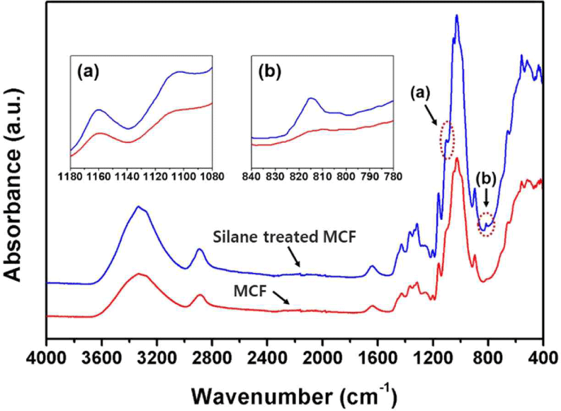
The FTIR spectra of the untreated and silane-treated MCFs are shown in Fig. 3. The absorption peaks of the typical cellulose were observed from the FTIR spectra of the untreated MCF. The stretching vibrations at 3,600–3,000 cm–1 indicate hydrogen bonds (–OH), and the stretching vibrations at 2,890 and 1,370 cm–1 indicate C–H bonds (Frone et al., 2011; Kim et al., 2019). The bending vibration at 1,050 cm–1 indicates C–H bonds, and the stretching vibration from the glycosidic bridges at 1,160 cm–1 indicates C–O–C bonds (Frone et al., 2011; Mahendiran et al., 2022; Pang and Ismail, 2013). On the other hand, new absorption peaks were observed from the FTIR spectra of the silane-treated MCF in comparison with that of the untreated MCF. The absorption peak at 1,100 cm–1 represents the stretching vibration of C-NH2 bond (Demjén et al., 1999; Mathialagan and Ismail, 2012; Pang and Ismail, 2013). Also, the absorption peak at 1,030 cm–1 is assigned to Si–O–Si bonds, and the absorption peak of Si–CH2 is observed at 815 cm–1, which is the characteristic peak of siloxane (Frone et al., 2011; Kim et al., 2012). The chemical changes obtained from the FTIR spectra are attributed to the chemical reaction between the hydroxyl groups of MCF and silanol by the silane treatment. A schematic showing the conversion of MCF surface from the hydrophilic to hydrophobic by the silane coupling reaction is shown in Fig. 4. Through silanization, hydrolysis of silane, condensation between silanols, and bond formation between siloxane and MCF fibers were sequentially achieved (Kim et al., 2012).
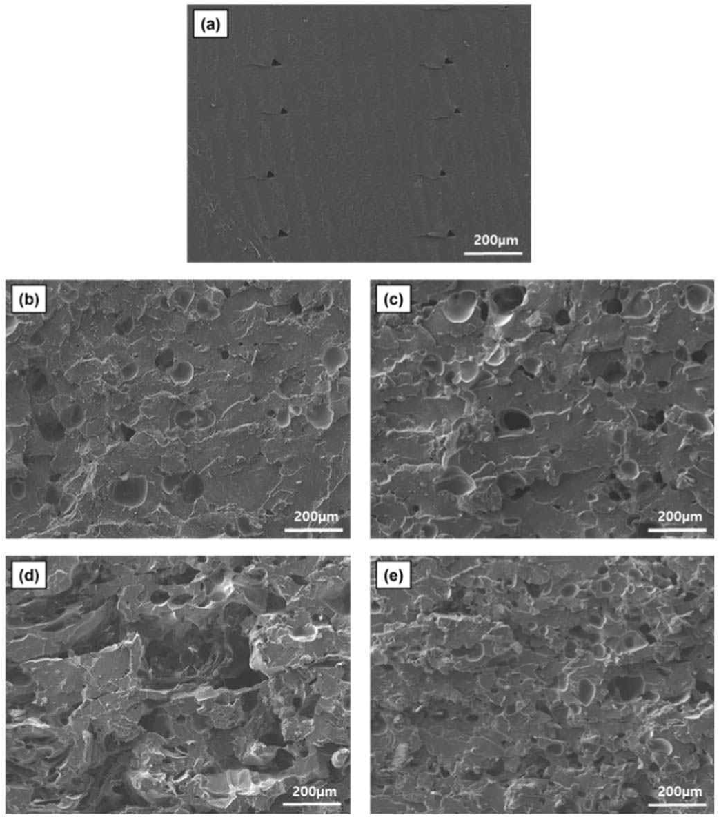
The scanning electron micrographs (100 × magnification) of various 3D-printed MCF/PLA composites are shown in Fig. 5. Fig. 5(a) shows the fractured surface of neat PLA, which exhibits a smooth surface. Good adhesions between the 3D printing layers were observed. Fig. 5(b) shows an image of the MCF/PLA composite with 5 wt.% untreated MCF. Some voids represent pull-out traces of MCF fillers. Scanning electron microscope (SEM) image of the MCF/PLA composite with 5 wt.% silane-treated MCF is observed in Fig. 5(c), showing similar surface features as untreated MCF filled composite due to the low filler content. Fig. 5(d) shows an image of the MCF/PLA composite with 10 wt.% untreated MCF. In Fig. 5(d), a rougher surface and larger pull-out traces are observed, which indicate not only poor interfacial adhesion between MCF and PLA matrix, but also the effect of aggregated MCF fibers. Fig. 5(e) shows an image of the MCF/PLA composite with 10 wt.% silane-treated MCF. Compared to Fig. 5(d), a less rough surface is observed because the hydrophilic functional groups on the MCF surfaces were reduced by the silane treatment of MCF.
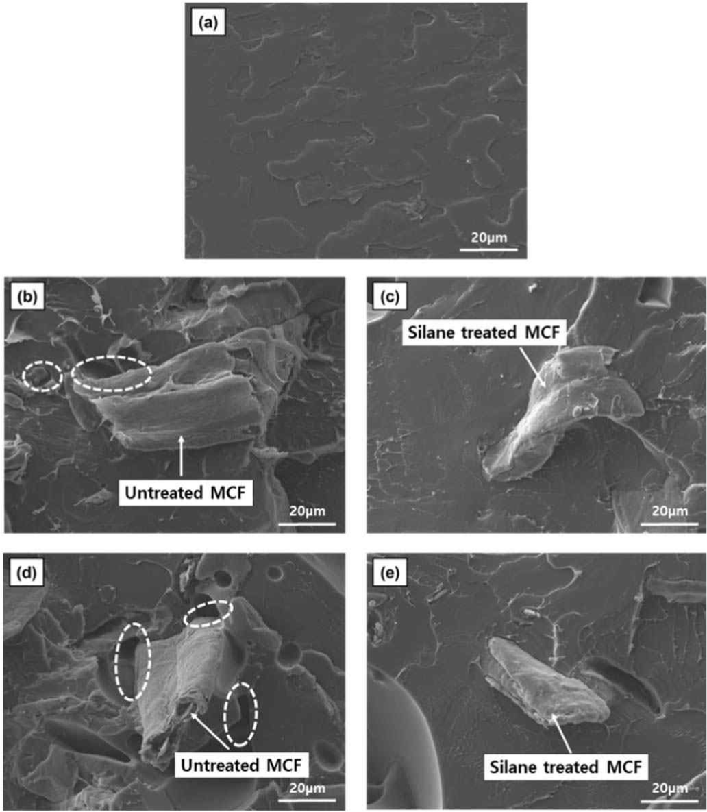
The scanning electron micrographs (1,000 × magnification) of various 3D-printed MCF/PLA composites are shown in Fig. 6. Fig. 6(a) shows the fractured surface of neat PLA, and a smooth surface is observed because no fillers are present. Fig. 6(b) and (d) show the images of MCF/PLA composites with untreated MCF. The images showed interfacial gaps (designated as dashed circles) between cellulose fibers and polymer due to the incompatibility between hydrophilic MCF and hydrophobic PLA. This incompatibility is expected to degrade the mechanical and thermal properties of MCF/PLA composites. Fig. 6(c) and (e) show the images of the MCF/PLA composites with silane-treated MCFs, which indicate improved interfacial adhesions between MCF and PLA matrix in contrast to those shown in Fig. 6(b) and (d). The silane-treated MCFs are also shown to be well trapped in the PLA matrix. Thus, better stress transfer could be expected. The SEM images show that the hydrophilic hydroxyl groups of MCF were substituted by hydrophobic functional groups resulted from the silane coupling reaction, which consequently led to improved interfacial adhesions between silane-treated MCF and hydrophobic PLA (Huda et al., 2008).
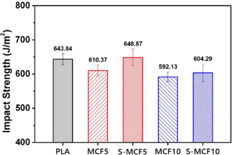
Mechanical properties are one of the important factors to evaluate the performance of 3D-printed objects. The impact strength of the various 3D-printed MCF/ PLA composites is shown in Fig. 7. The impact strength of the 3D-printed MCF/PLA composites was reduced by the incorporation of untreated MCF due to the poor interfacial adhesion between hydrophilic MCF and hydrophobic PLA matrix. Further, the stress caused by the external impact was concentrated in the gaps between MCF and PLA (Koohestani et al., 2017). In addition, the presence of fibers aggregated by the hydroxyl groups of the untreated MCF and the mobility of the restricted PLA resulted in quasi-brittle fracture behavior (Zulkifli et al., 2015). On the other hand, the impact strengths of S-MCF5 and S-MCF10 specimens (648.87 and 604.29 J/m2) exhibited improved results compared to those of MCF5 and MCF10 (610.37 and 592.13 J/m2). From the abovementioned FTIR spectra and SEM images, improved interfacial interaction between MCF and PLA matrix was achieved by the silane treatment, which enabled stress transfer and improved impact strength (Gwon et al., 2010). However, the 3D-printed specimens had lower impact strength than conventionally molded samples due to the gaps between layers. No remarkable improvement in strength values was observed compared to neat PLA.
The tensile properties of the various 3D-printed MCF/ PLA composites are shown in Fig. 8. For tensile strength, all the 3D-printed MCF/PLA composites exhibited reduced features compared to neat PLA. From the abovementioned SEM images, bigger voids were particularly observed in the 3D-printed MCF/PLA composites with 10 wt.% untreated MCF due to the poor interfacial adhesion between MCF and PLA matrix, which easily broke during the tensile test (Chun et al., 2012). But, among the 3D-printed MCF/PLA composites, S-MCF5 and S-MCF10 specimens (35.06 and 31.62 MPa) with silane-treated MCF exhibited improved tensile strength compared to MCF5 and MCF10 (29.85 and 23.68 MPa) with untreated MCF because the hydroxyl groups on the MCF surface were replaced with hydrophobic functional groups by the silane treatment, thereby increasing the hydrophobicity. Thus, they demonstrated improved interfacial compatibility with the PLA matrix (Liu et al., 1997). As shown in Fig. 8, the whole 3D-printed MCF/ PLA composites demonstrated an increased tensile modulus compared to neat PLA. According to the study by Agrawal et al., surface treatment using chemical reactions affects the mechanical properties of natural fibers, especially stiffness improvement by fiber reinforcement in composites (Agrawal et al., 2000). The tensile modulus of the 3D-printed MCF/PLA composites was improved by the presence of MCF, and the effect of silane-treated MCF was more pronounced. Thus, S-MCF10 demonstrated the highest tensile modulus value (5,869.05 MPa).

The flexural properties of the various 3D-printed MCF/PLA composites are shown in Fig. 9. All the 3D-printed MCF/PLA composites exhibited a reduced flexural strength compared to neat PLA. This result is similar to that of the tensile strength reduced by the incorporation of MCF fillers. S-MCF5 and S-MCF10 specimens (58.12 and 50.90 MPa) with silane-treated MCF demonstrated improved flexural strength values compared to MCF5 and MCF10 (54.46 and 46.49 MPa) with untreated MCF. It is associated with the interfacial adhesion, which was improved by the silane treatment, exerted an improvement effect on the flexural strength (Ifuku and Yano, 2015). As shown in Fig. 9, MCF5 specimen (2,212.14 MPa) demonstrated increased flexural modulus compared to neat PLA (2,176.30 MPa). S-MCF5 (2,441.67 MPa) also exhibited more improved flexural modulus than neat PLA and MCF5. This result is similar to the improvement of tensile modulus by the incorporation of MCF mentioned above. It is considered that the movement of polymer chain was suppressed by the incorporation of MCF, thereby increasing the rigidity of the 3D-printed MCF/PLA composites. We also believe that the enhancement of interfacial adhesion by silane treatment has an effect on the increase in flexural modulus (Huda et al., 2008). However, in contrast to the tensile modulus results, both MCF10 and S-MCF10 specimens (1,975.73 and 2,145.15 MPa) with increased MCF content demonstrated lower flexural modulus than neat PLA (2,176.30 MPa). These are probably attributed to the poor deposition between the 3D printing layers caused by the bigger voids for MCF10 and the more voids for S-MCF10, as shown in the abovementioned SEM images. Among the MCF/PLA composites, MCF10 specimen exhibited the lowest flexural modulus, suggesting that this result was caused by the aggregation of cellulose fibers. On the other hand, S-MCF10 specimen showed improved flexural modulus compared to MCF10 due to the silane treatment effect.

From the mechanical property results, MCF/PLA composites with silane-treated MCF showed better properties than those with untreated MCF. This result indicates that surface modification effects by the silane coupling agent could be adequately achieved in 3D-printed MCF/PLA composites.
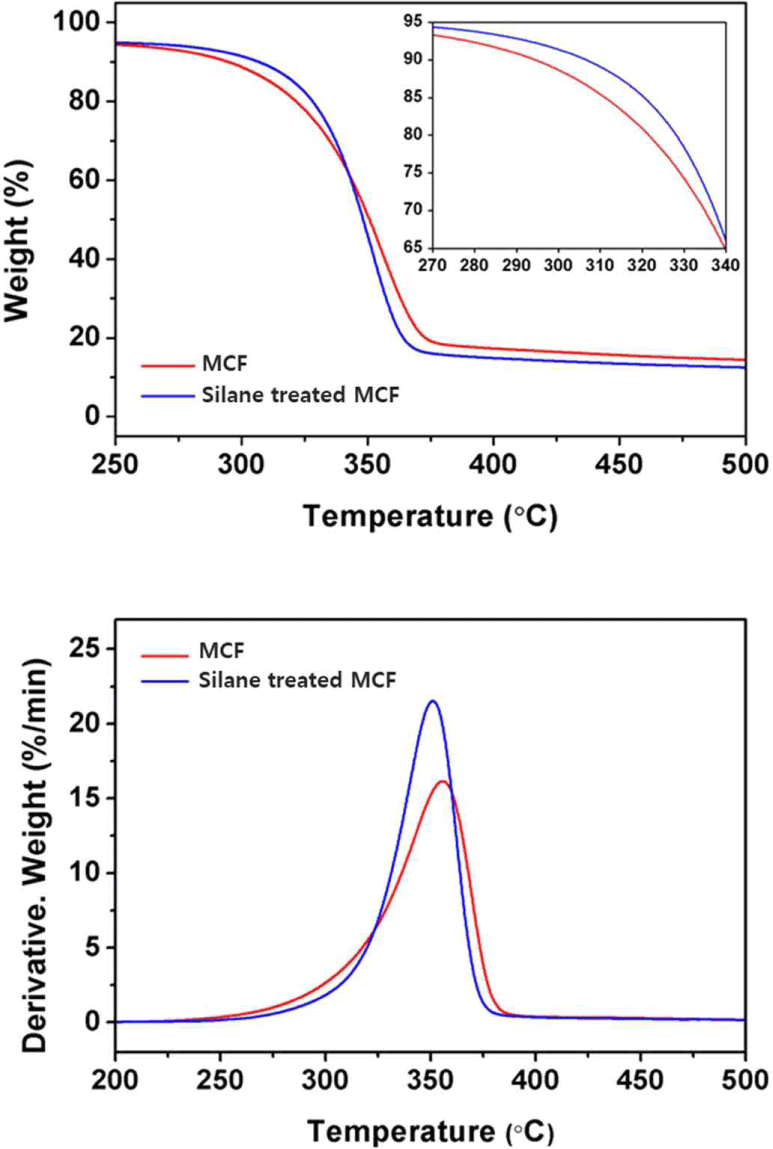
The TG and derivative TG (DTG) curves of the untreated and silane-treated MCFs are shown in Fig. 10, respectively. The total TGA results are listed in Table 2. T95 and T50 refer to the temperatures at which the remaining masses of the composites were 95% and 50%, respectively. The peaks of stage one in the DTG curves shown in Fig. 10 were due to the thermal decomposition of cellulose, and the measured peak maximum temperatures are indicated as Tmax. The T95 values of the untreated and silane-treated MCFs were measured as 217.77°C and 243.27°C, respectively, and demonstrated an initial thermal decomposition temperature difference of approximately 26°C. The thermal stability of the silane-treated MCF was improved in comparison with that of the untreated MCF until a weight loss of around 40%. This result demonstrated an improved thermal stability from the beginning to the middle after the start of the thermal decomposition. Delaying early thermal decomposition in the material is very important. The thermal decomposition at this stage is due to the decomposition of cellulose, which is the result of dehydration reaction among or within the molecules. The hydroxyl groups in cellulose are stable as leaving groups, but heat protonates the hydroxyl groups in natural fibers, converting them into higher leaving groups. Therefore, hydroxyl groups are released, increasing the possibility of thermal decomposition. However, silane-treated cellulose has been considered to have improved thermal stability due to the relatively small number of hydroxyl groups because hydroxyl groups on the surface of cellulose are replaced with other functional groups through silane coupling reactions (Lu et al., 2008; Moon et al., 2011).
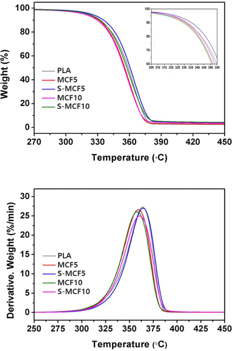
The TG and DTG curves of the various MCF/PLA composites are shown in Fig. 11. The total TGA results are listed in Table 2 as well. The peaks of stage one in the DTG curves observed in Fig. 11 were due to the thermal decomposition of PLA and cellulose, and the Tmax values of neat PLA and MCF did not exhibit a large difference and were shown as one peak. The MCF/ PLA composites with silane-treated MCF exhibited an improved thermal stability compared to the MCF/PLA composites with untreated MCF. As a result, the TG and DTG curves shifted to the right, and the T95, T50, and Tmax values accordingly increased. This result indicates that the interfacial molecular chain between MCF and PLA matrix was tightly connected by the silane treatment and that higher energy was required to interfere with the chemical and physical interactions, thereby improving the heat resistance (Qian and Sheng, 2017). Comparisons of the TGA data of the MCF and neat PLA listed in Table 2 reveal that the thermal stability of PLA was better. Thus, the thermal stability of the MCF/ PLA composites with MCF is expected to decrease compared to that of neat PLA. However, S-MCF5 specimen exhibited the improvement of thermal stability compared to neat PLA. As a result, the TG and DTG curves shifted to the right and the T95, T50, and Tmax values increased. This is probably due to the enhanced interfacial interactions between the surface-modified MCF and PLA matrix, and consequently provided the improved thermal stability to the MCF/PLA composites.
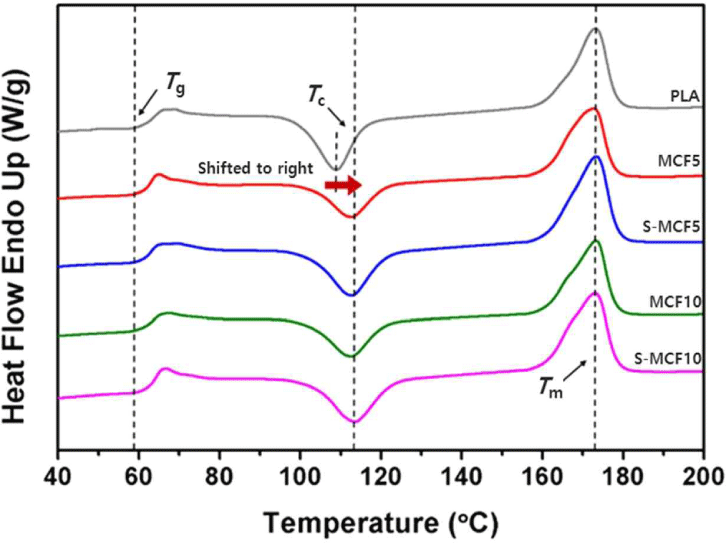
The heating-run curves of the various MCF/PLA composites obtained by the DSC analysis are shown in Fig. 12. The total DSC characteristics of the MCF/PLA composites are listed in Table 3. The Tg values of the MCF/PLA composites did not show any difference in the presence of MCF and appeared almost similar. Glass transition of polymers has been known to depend on various factors such as the molecular weight of the polymers, interaction among molecules, and crosslink density among the molecules (Krishnamachari et al., 2009). Therefore, Tg can be varied by the presence of a filler, however, because of the PLA, which occupy a high fraction of at least 90 wt.%, Tg values of the MCF/PLA composites are considered to be similar to that of neat PLA (Frone et al., 2013). Tm values of the MCF/PLA composites were measured to be similar regardless of the presence of untreated or silane-treated MCF, which was considered to be similar to abovementioned Tg. Xc values of the MCF/PLA composites increased compared to that of neat PLA because MCF acted as a heterogeneous nucleating agent in the PLA matrix to promote nucleation (Suksut and Deeprasertkul, 2011). Xc slightly increased as the MCF content in the PLA matrix increased. It probably seems to be due to the increase in the nucleation sites of MCFs, which served as nucleating agents, with increasing MCF content. However, Xc of the MCF/PLA composites with silane-treated MCF was lower than that of the MCF/ PLA composites with untreated MCF because of the stronger adhesion between MCF and PLA matrix by the silane treatment, which means that the movement of the PLA chains close to the silane-treated MCF could be limited and thus disrupted the crystallization process (Frone et al., 2013). Tcc of the MCF/PLA composites was higher than that of neat PLA because of the presence of MCF. Xc of the MCF/PLA composites was improved by the presence of MCF, which was expected to promote nucleation by acting as a heterogeneous nucleating agent. Therefore, Tcc was also expected to decrease due to the effect of the accelerated crystallization. However, Tcc increased due to the presence of untreated or silane-treated MCFs in the MCF/PLA composites, which could have reduced the mobility of the molecular chains and thus did not accelerate the formation of crystallization but consequently improved Xc (Gwon et al., 2010).
4. CONCLUSIONS
In this study, MCF was surface modified using a silane coupling agent (i.e., APTES) and then, MCF/PLA composites were reinforced with untreated or silane-treated MCFs, successfully fabricated as filaments for FFF 3D printing and printed using a FFF 3D printer. After that, effects of silane treatment on the optical, morphological, mechanical, and thermal properties of FFF 3D-printed composites were analyzed. The observed key conclusive results are as follows:
The silane treatment of MCF was verified by the FTIR spectra, which demonstrated that the hydrophobic characteristics increased through a condensation reaction between hydrolyzed silane and the hydroxyl groups of MCF. The increase in hydrophobic properties of silane-treated MCF was confirmed by FTIR spectra of the new absorption peaks at 1,100 cm–1, 1,030 cm–1, and 815 cm–1 representing C-NH2, Si–O–Si, and Si–CH2 bonds, respectively. According to the SEM images, improved interfacial adhesions between silane-treated MCF and the PLA matrix were observed. Also, reduced voids were observed from the fractured surface of the S-MCF specimens. The impact, tensile and flexural strengths of the 3D-printed MCF/PLA composites with silane-treated MCF were improved compared to those of the 3D-printed MCF/PLA composites with untreated MCF. The highest values of tensile and flexural moduli were observed at S-MCF10 (5,784.77 MPa) and S-MCF5 (2,441.67 MPa), respectively. The TGA result of the silane-treated MCF showed the better thermal stability by delaying the initial thermal decomposition temperature compared to the untreated MCF. The thermal decomposition temperature difference at T95 was around 26°C. In DSC results, the presence of untreated MCF in MCF/PLA composites led to increased Xc by acting as a heterogeneous nucleating agent. However, the presence of silane-treated MCF in the MCF/PLA composites led to stronger interactions between MCF and PLA matrix, which rather limited the crystallization process.
