1. INTRODUCTION
In wood construction, the shear wall is an important component that provides lateral force resistance. A shear wall includes studs and sheathing, which are typically used in light-frame timber construction; additionally, a shear wall can be composed of mass timber, such as cross-laminated timber (CLT). Interest in CLT is increasing, and studies regarding CLT are being conducted actively in Korea. Yang et al. (2021) investigated the research trends pertaining to hybrid CLT to enhance the rolling shear strength of CLT. Jung et al. (2020) evaluated the effect of glass fiber-reinforced connection on the horizontal shear strength of CLT walls. Choi et al. (2021) evaluated the flexural performance of CLT using the plywood bonding method of ply-lam CLT. However, the shear wall of the light-frame timber construction has not been investigated sufficiently.
In light-frame timber construction, the shear wall is one of most important components that provide seismic resistance to the entire timber structure. The seismic resistance of a shear wall can be expressed as the story deformation, calculated using Equation (1), in accordance with KDS 41 50 (Ministry of Land, Infrastructure and Transport, 2018a). It is expressed as the sum of four elements, including the effects of studs, sheathing, nails, and anchoring.
where
A: cross-sectional area of end studs (mm2)
b: length of wall (mm)
da: deflection due to anchorage (rotation and slip of hold-down connections) (mm)
E: modulus of elasticity of end stud (N/mm2)
en: nail slip at a particular load per nail (mm)
Gt: through-thickness shear rigidity of sheathing panel (N/mm)
h: wall height (mm)
v: applied shear force per unit length (N/mm)
△: racking deformation of shear wall (mm)
According to Wang (2009), nail slip (Dn) constitutes 76.81% of the total deformation of a shear wall (Dt) at the ultimate load. Other factors such as the bending of stud (Ds), shear of sheathing (Dp), and anchorage deformation (Da) for calculating the story deformation of a shear wall do not contribute significantly to the total racking deformation of a shear wall, i.e., 2.92% (Ds/Dt), 18.37% (Dp/Dt), and 1.90% (Da/Dt). Jang (2002) proposed two theoretical models to predict the racking resistance of shear walls and evaluated their accuracy by comparing the results predicted by models and test results. Hwang and Park (2008) tested the shear performance of nailed joints composed of structural lumber, OSB sheathing, and helically threaded nails and estimated their yield strength and slip modulus. Oh (2013) evaluated the withdrawal and lateral resistance of a nail joint composed of dimension lumber and OSB sheathing. Recently, studies regarding fasteners other than nails have been conducted. Lee et al. (2021) evaluated the withdrawal resistance of screw-type fasteners based on the lead-hole size, grain direction, screw size, screw type, and species. Lee et al. (2022) evaluated the bearing strength of self-tapping screws based on the grain direction of domestic Pinus densiflora.
According to KDS 42 50 10 (Ministry of Land, Infrastructure and Transport, 2018b), shear walls shall be constructed by attaching one 11 mm or thicker structural wood-based panels to the structural lumber stud frame using 8d nails fixed with a nail spacing of 150 mm along the edge and 300 mm in the field. If the aspect ratio of the shear wall exceeds 2:1 (height:length), then the nailing shall be reinforced with a nail spacing of 100 mm along the edge and 200 mm in the field. According to KDS 42 50 10, the minimum required length of a shear wall is limited to 600 mm such that it can be recognized as a seismic-resisting component.
Although light-frame timber shear walls can be used in the seismic design of small-scale residential timber buildings (in accordance with KDS 42 50 10), only one conventional standard type of shear wall is available even though unlimited numbers and types of timber shear walls are available worldwide for timber construction. The current study is performed to evaluate the seismic performance of various types of shear walls with reinforced nailing and sheathing attached to both sides of the stud frame.
2. MATERIALS and METHODS
Shear wall specimens, as shown in Fig. 1, were prepared via the light-frame timber construction method using 2 × 6 studs. The framing lumber was northern SPF no. 2 lumber (Jang and Lee, 2019b). The stud spacing applied to the shear wall specimen was 610 mm, and 12d nails were used to connect the framing members. The sheathing material used for the shear wall was structural OSB measuring 11.1 mm thick, which was attached to the frame using 8d nails.
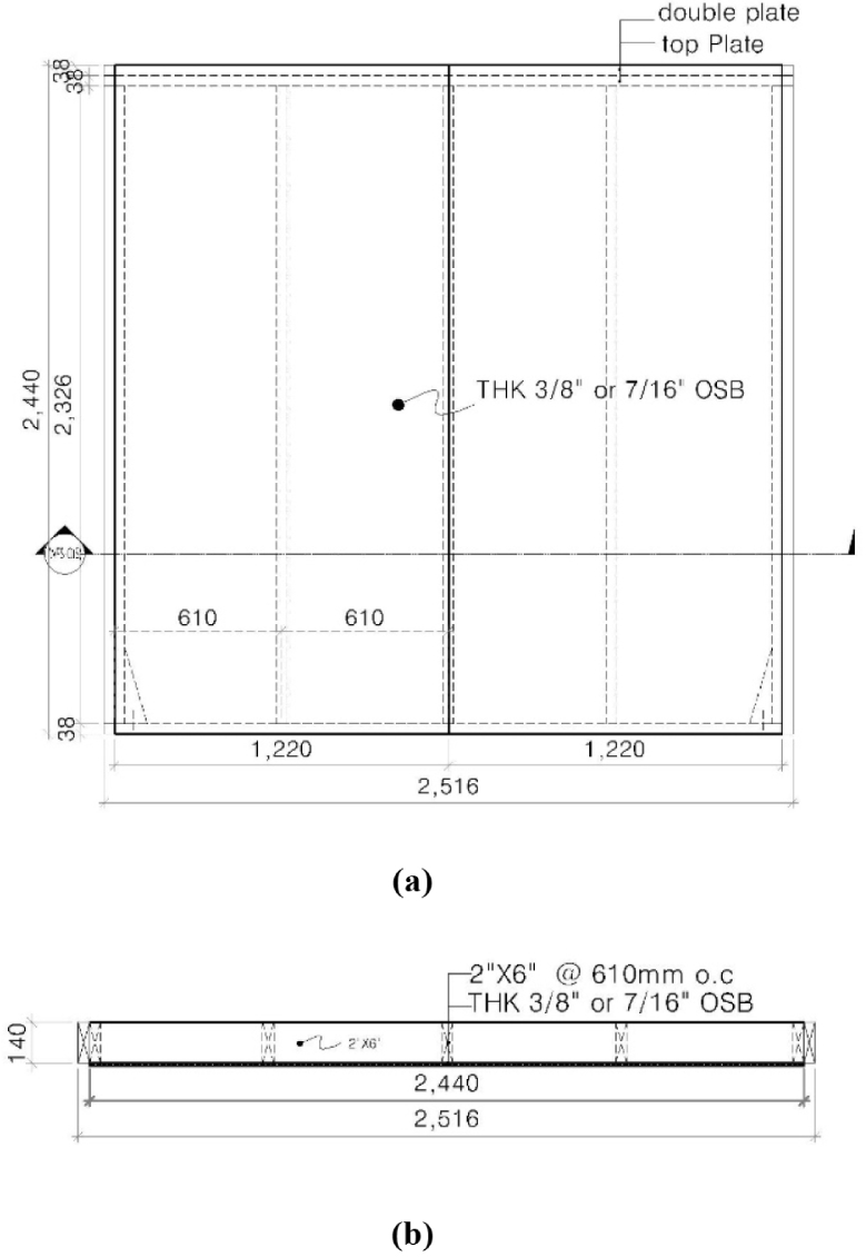
The cross-section of the shear wall specimen was 2,440 mm × 2,440 mm but its total length was 2,516 mm because 2 × 6 studs were added at both ends to accommodate testing. As the sill plate, 90 mm × 140 mm lumber was installed at the bottom of the specimen using anchor bolts with a diameter of 16 mm at a spacing of 760 mm.
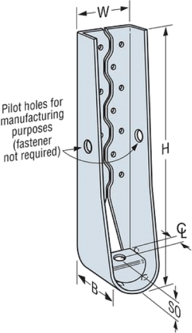
At both ends of the shear wall specimen, a Simpson strong-tie hold-down connector HDU2-SDS2.5 (as shown in Fig. 2 and specified in Table 1) conforming to hold-down with a round-shaped basement (as specified in KS F 4514) was fixed to establish a connection with the foundation (steel base framing of the testing facility) through the sill plate.
| Type | Dimensions | ||||
|---|---|---|---|---|---|
| W (mm) | H (mm) | B (mm) | CL (mm) | SO (mm) | |
| Hold-down | 7.62 | 33.49 | 8.25 | 3.33 | 3.49 |
To evaluate the effects of nail spacing and number of sheathing (one or two surfaces), the shear wall specimens were prepared as specified in Table 2. For all six types of specimens, 8d nails were used to establish connections between the framing lumber and sheathing panels. For the shear wall specimens with one sheathing, various nail spacings, such as 150 mm (edge)–300 mm (field) (WFS-150), 100 mm (edge)–200 mm (field) (WFS-100), and 75 mm (edge)–150 mm (field) (WFS-075), and 50 mm (edge)–100 mm (field) (WFS-050), were applied to evaluate the effect of nail spacing. In addition, the shear wall specimens with two sheathing, one on each of the front and back surface, were constructed with two different nail spacings, i.e., 150 mm (edge)–300 mm (field) (WFS-B150) and 100 mm (edge)–200 mm (field) (WFS-B100).
| Symbol | Sheathing | Nail | |
|---|---|---|---|
| Size | Spacing (mm) | ||
| WFS-150 | OSB sheathing on one side | 8d | 150–300 |
| WFS-100 | 100–200 | ||
| WFS-O75 | 75–150 | ||
| WFS-O50 | 50–100 | ||
| WFS-B150 | OSB sheathing on both sides | 8d | 150–300 |
| WFS-B100 | 100–200 | ||
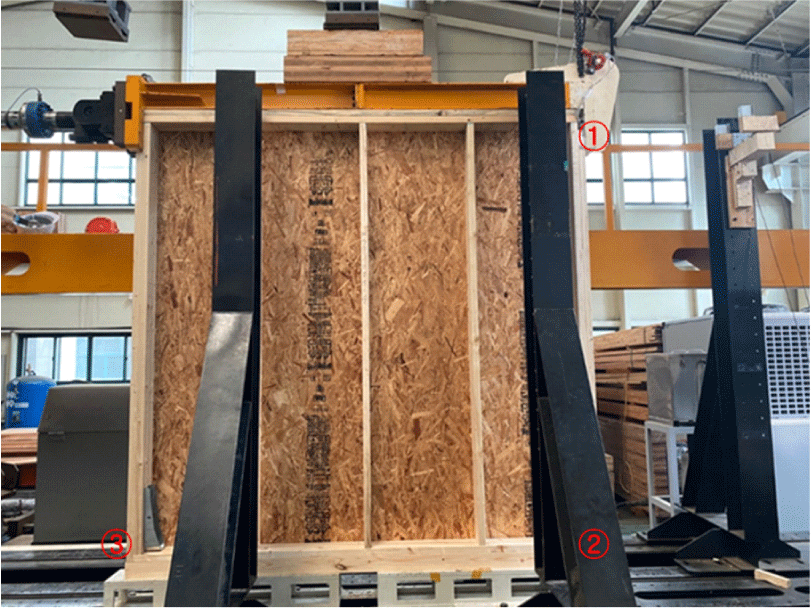
A lateral-load resistance test was performed in accordance with KS F 2154 (Korean Standards Association, 2016; Lee et al., 2021) and ASTM E 2126 (ASTM, 2019), as shown in Fig. 3. The loading block was placed on top of the specimen to deliver the lateral load uniformly via the top length of the specimen. During the test, displacement was measured using three linear variable differential transformers (LVDTs) attached at locations ①, ②, and ③ shown in Fig. 3, among which the LVDT at ① was used to measure the horizontal displacement at the top of the specimen, the LVDT at ② was used to measure the horizontal slip at the bottom of the specimen, and the LVDT at ③ was used to measure the vertical displacement at the bottom of the specimen due to the tensile force caused by the overturning moment.
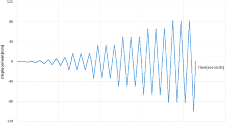
The lateral loading schedule (in accordance with ASTM E 2126) applied to the specimen involved quasi-static cyclic loads (as shown in Fig. 4). In particular, the schedule was composed of displacement-controlled loading functions involving 11 loading steps, e.g., displacements of 1.04, 2.08, 4.16, 6.25, 8.33, 16.66, 33.33, 50, 66.66, 83.33, and 100 mm. Among the 11 loading steps, the first five loading steps were composed of one loading cycle to allow the adjustment of the specimen before the actual testing, whereas the 6th to 11th loading steps were composed of three loading cycles, and the cyclic frequency was 0.2 Hz.
The shear strength and shear modulus were calculated based on the test results using Equations (2) and (3) in accordance with KS F 2154, respectively.
where
Su: shear strength (kN/m)
Ppeak: maximum load or the load at 50 mm displacement (kN)
b': length of specimen (m)
where
G: shear modulus (kN/mm)
a: height of specimen (m)
b': length of specimen (m)
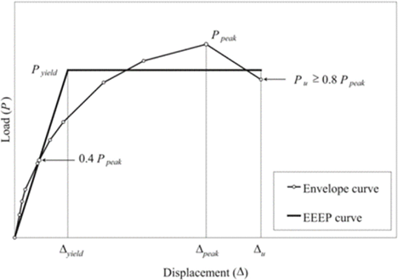
The yield point was obtained in accordance with ASTM E 2126 by equating the area under the envelope curve to the area under the equivalent energy elastic–plastic (EEEP) curve, as shown in Fig. 5. EEEP curves can be constructed by extending the initial sloped line connecting between the origin and 0.4 Ppeak point to coincide with the second horizontal line determined such that the area under EEEP curve equals the area under the envelope curve. The point where the initial sloped line and the second horizontal line coincides is defined as the yield point and the load at the yield point is the yield-point load, which can be used as the design value for the lateral-load resistance of shear walls.
3. RESULTS and DISCUSSION
Based on results of lateral-load tests of the shear wall specimens, load–displacement diagrams similar to that shown in Fig. 6 can be obtained for each shear wall specimen.
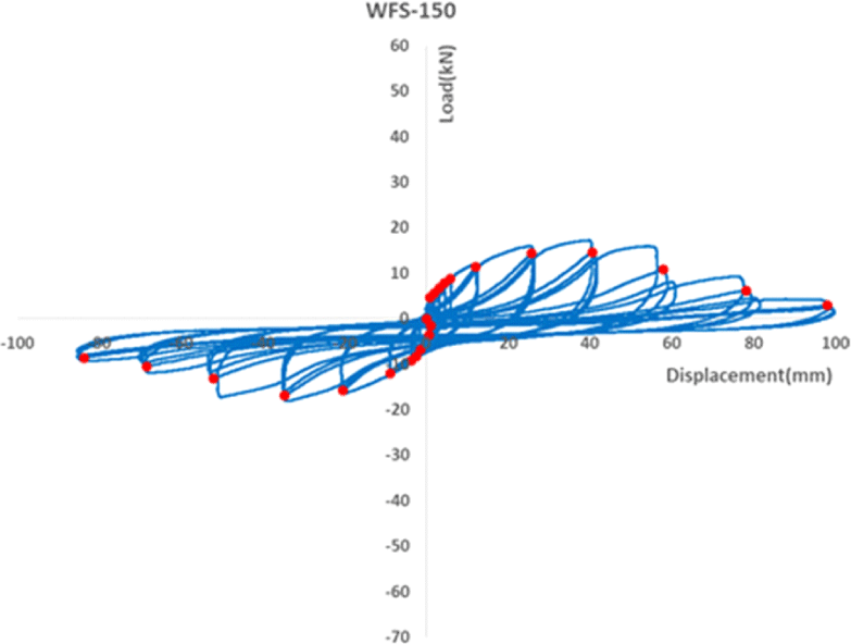
The load–displacement diagram shown in Fig. 6 can be converted into an envelope curve by identifying the peak points of the second loading cycle (the points shown as dots in Fig. 6) in the three loading cycles of each loading step and connecting them.
The load–displacement diagrams obtained from the lateral-load resistance tests (Jang and Lee, 2019a) for specimens WFS-150, WFS-100, WFS-O75, and WFS-O50 were combined in one graph, as shown in Fig. 7.
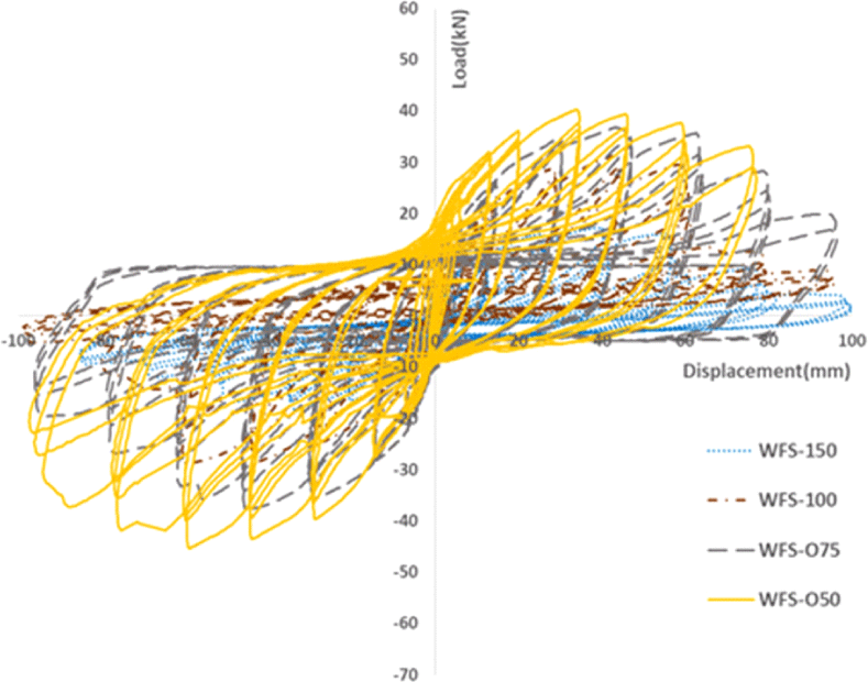
Based on Fig. 7, specimen WFS-O50 showed the highest lateral-resistance among the four shear wall specimens with one sheathing attached on one side of the framing, and the lateral resistance decreased in the order of WFS-O50, WFS-O75, WFS-100, and WFS-150. Therefore, one can conclude that the lateral resistance of a shear wall increases as the nail spacing applied for fixing the sheathing panel to the framing decreases.
Using the results of lateral-load resistance tests of the shear wall specimens with two sheathing panels (specimens WFS-B150 and WFS-B100), one on each side of the frame, a load–displacement diagram similar to that shown in Fig. 8 can be constructed. To evaluate the effects of the number of sheathing panels installed on the shear wall, the load–displacement diagrams for the shear wall specimens with two sheathings (WFS-B150 and WFS-B100) were combined with those for the shear wall specimens with one sheathing and the same nail spacing (WFS-150 and WFS-100), as shown in Fig. 9.
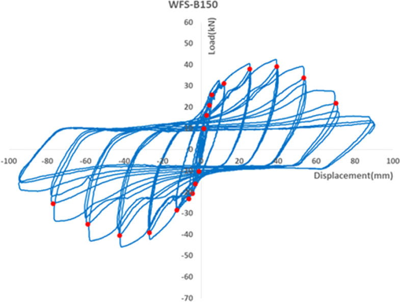
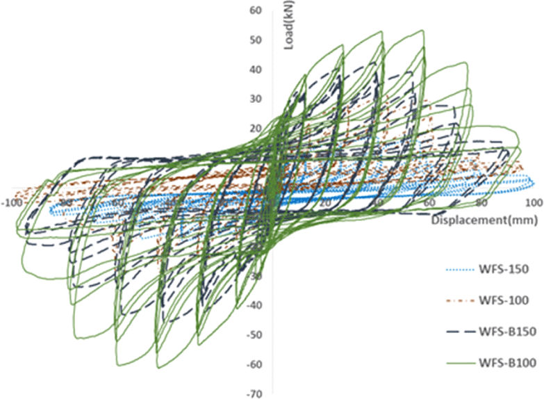
Based on Fig. 9, the shear wall specimens with two sheathings (WFS-B150 and WFS-B100) indicated higher lateral resistance than the shear wall specimens with one sheathing (WFS-150 and WFS-100). Therefore, one can conclude that the shear wall with two sheathing panels, one on each side of the frame, possesses higher lateral resistance than the shear wall with one sheathing.
Even though the lateral resistance of the shear walls can be compared using the load–displacement diagrams (as shown in Figs. 7 and 9), the exact shear modulus and shear strength can be calculated using Equations (2) and (3), respectively, in which the input data can be obtained from the envelope curves converted from the load–displacement diagrams. For example, the load–displacement diagrams shown in Figs. 6 and 8 (for specimens WFS-150 and WFS-B150 specimens, respectively) can be converted into the envelope curves as shown in Figs. 10 and 11, respectively, by connecting the peak points for the second loading cycle of each loading step.
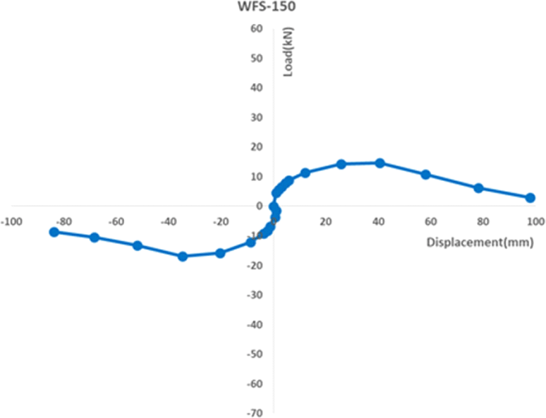
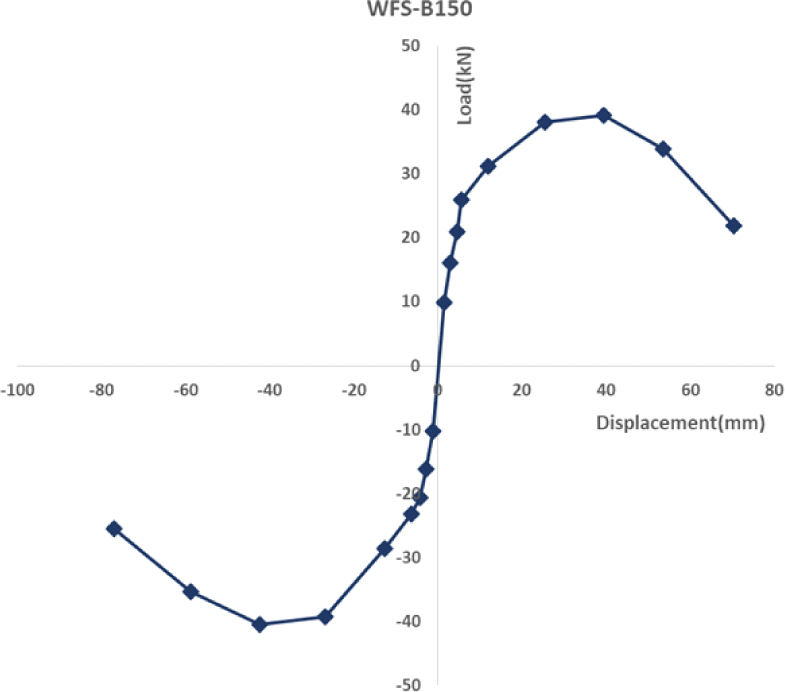
Using the envelope curves shown in Figs. 10 and 11, the input values for Equations (2) and (3) can be obtained to calculate the shear modulus and shear strength of the shear wall specimens. However, the design values for the lateral resistance of the shear walls shall be obtained from the yield-point loads, which can be obtained from the EEEP curve converted from the envelope curve. The envelope curves presented in Figs. 10 and 11 show both regions under tensile (pushing) and compressive (pulling) cycles.
However, to convert the envelope curve into an EEEP curve reflecting both pushing and pulling characteristics, these two curves shall be combined as one average envelope curve as shown in Fig. 12. Meanwhile, the EEEP curve can be constructed based on the average envelope curve.
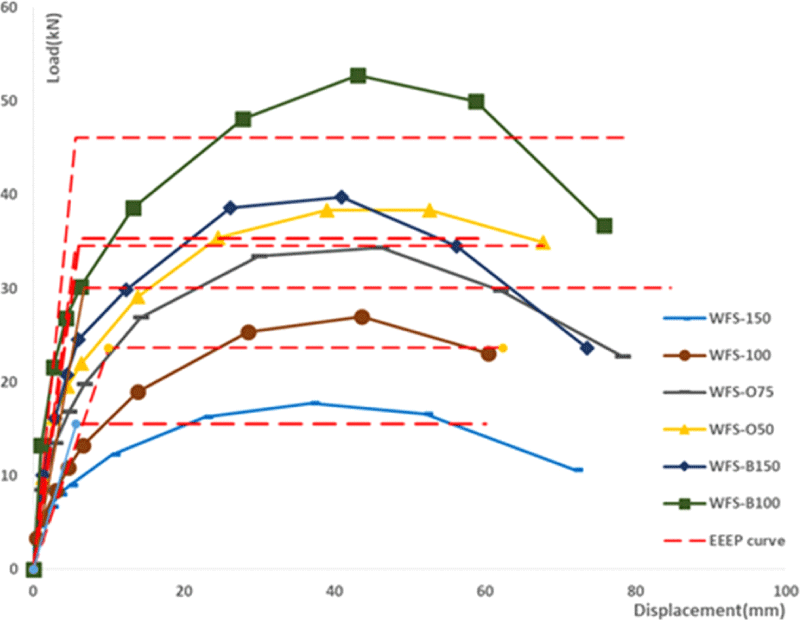
In Fig. 12, the point where the initial sloped line and the second horizontal line coincide represents the yield point of the shear wall, which can be used as the design value for the shear wall. The lateral-load resistance properties for the six types of shear wall specimens used in this study, including the maximum load (Ppeak), yield-point load (Pyield), shear modulus, and shear strength, are listed in Table 3.
The maximum load and yield-point load indicated in Table 3 were obtained from the average envelope curve shown in Fig. 12, and shear strength and shear modulus were calculated using Equations (2) and (3), respectively. As shown in Table 3, the maximum load (Ppeak), yield-point load (Pyield), shear modulus, and shear strength increased in the order of WFS-150, WFS-100, WFS-075, WFS-050, WFS-B150, and WFS-B100. Therefore, one can conclude that increased nailing reinforcement (decreased nail spacing) provided robustness to the shear wall against the lateral load, whereas the attachment of an additional sheathing increased the lateral-load resistance of the shear wall. When the nail spacing decreased from 150 mm (edge)–300 mm (field) (WFS-150) to 50 mm (edge)–100 mm (field) (WFS-050), the ultimate shear strength doubled (an increase of 202%). When an additional sheathing was attached on the other side of the shear wall without decreasing the nail spacing (WFS-B150), the results showed similar reinforcement effects of the lateral-load resistance (an increase of 206% in the ultimate shear strength). When an additional sheathing was attached on the other side of the shear wall and the nailing reinforcement was implemented at a nail spacing of 100 mm (edge)–200 mm (field) (WFS-B100), the lateral-load resistance of the shear wall specimen was 2.7 times higher than that of the standard shear wall (WFS-150), which was the highest among six types of shear wall specimens analyzed in this study.
4. CONCLUSIONS
In this study, the lateral-load resistance of various types of shear walls, in which nailing reinforcement by decreased nail spacing and incorporating an additional sheathing were applied, was tested in accordance with KS F 2154 and ASTM E 2126. The test results showed the following:
-
All the lateral-load resistance properties showed the same increasing trend in the order of WFS-150, WFS-100, WFS-075, WFS-050, WFS-B150, and WFS-B100.
-
By implementing nailing reinforcement (i.e., decreasing the nail spacing), the lateral-load resistance of the shear wall increased.
-
Incorporating an additional sheathing on the other side of shear wall increased the lateral-load resistance of the shear wall.
-
When nailing reinforcement was implemented by decreasing the nail spacing from 150 mm (edge)–300 mm (field) to 50 mm (edge)–100 mm (field), the shear strength doubled.
-
When an additional sheathing was attached on the other side of the shear wall, the shear strength doubled as compared with the case without nailing reinforcement.
-
Among the six types of shear wall specimens used in this study, WFS-B100 showed the highest lateral-load resistance, which was 2.7 times higher than that of the standard shear wall (WFS-150).

