1. INTRODUCTION
Cross-laminated timber (CLT) panels with three or more layers are fabricated in such a way that the fiber direction of the interlayer laminae is perpendicular. These panels allow ease of handling during construction and a high level of prefabrication because their specific weight is only about a fifth of that of reinforced concrete (Bogensperger et al., 2011; Mohammad et al., 2012). These advantages have recently established CLT as a representative engineered timber, which enables the construction of middle-to high-rise buildings, as in the reinforced-concrete method. The CLT construction entails bearing-wall-type structures requiring high structural performance, in which the CLT panels with a large cross-section simultaneously support the vertical and horizontal loads. Various studies related to this construction method have been conducted.
Tavoussi et al. conducted horizontal shear strength tests for CLT walls laminated at various angles, where major cracks in the CLT walls were not observed although differences in stiffness occurred depending on the angle of laminae (2008). Sanders developed an interlocking CLT wall and found that sufficient horizontal shear strength could be achieved in low-story structures because not only do they have high strength, they also assure that full destruction will not occur even under a higher-level horizontal load (2011). The horizontal shear tests for CLT walls in previous studies verified that CLT walls have high stiffness and inplane compressive strength comparable to steel even though they are produced by bonding multiple lamina (Jang and Lee, 2019). Kitamori et al. demonstrated through analysis that unlike in Europe where CLTs of a large cross-section can be produced, small CLT panels are appropriate for transportation or fabrication in Japan. Therefore, for higher horizontal shear strength of CLT walls, they attempted to apply high-strength lag bolt to the support connection of CLT walls. As a result, the cross lamination between laminae in the CLT connection was not large, prompting the conclusion that it is important to examine the accurate strength of each connection (2014). Nakashima et al. conducted connections between CLT walls and floors using a steel plate and a drift pin. These authors reported that the connection made using a steel plate and a drift pin has low dependence on the angular orientation owing to the cross lamination effect of laminae. High ductility is also observed because failure along the fiber direction of each lamina can be prevented, in contrast to the study of Kitamori et al. Furthermore, they also reported that a brittle failure occurred under a cyclic load in the screw connection unlike the steel plate and drift pin connection (2014). Popovski et al. performed horizontal shear tests for CLT walls according to the various connections of the support, and reported that proper seismic performance could be achieved even by using metal brackets and screws. In addition, they reported that CLT wall-to- floor connection using long screws was not appropriate for a high seismic zone because of lack of ductility capacity (2010). In the final analysis, the factor influencing the horizontal shear strength of CLT walls is the connection between the CLT walls and floors or the edge connection between the CLT walls, rather than the CLT itself (Song et al., 2019). Hummel et al. analyzed the behaviors of CLT walls according to the combination of anchorage and connection under cyclic loading. The test result confirmed that the support condition had a direct effect on the wall’s cyclic behavior. Moreover, they reported that the contribution of slip and rocking to the overall deflection of the CLT wall affected the damping capacity of the wall element under cyclic loading (2013). In particular, the connections between CLT walls and floors play the critical role of providing strength, stiffness, and ductility to structures, which is closely related to the maintenance of structural integrity, strength, and stability of buildings. Therefore, sustained research on CLT walls and floors is required, especially on the improvement of horizontal strength compared to when existing connection methods are used under cyclic loading.
In this study, the horizontal shear strength test was performed on the CLT walls reinforced with glass fiber- based reinforcement to improve the performance of the CLT connection system.
This study also conducted horizontal shear tests for CLT walls with glass fiber-based connection reinforcement under monotonic and cyclic loading.
2. MATERIALS and METHODS
The CLT connection system was made by attaching glass fiber-based reinforcement to the connection zone of a CLT core lamina, as shown in Fig. 1. Three types of glass fiber reinforced core laminae were produced according to the type of glass fiber reinforcement:
Series-GS: Fabricated by reinforcing longitudinal glass fibers with GFRP extruded in a 1.2-mm-thick sheet together with epoxy resin
Series-GT: Fabricated by reinforcing 4-mmwide glass fiber bundles in the form of textile.
Series-GTS: Fabricated by reinforcing fabric- type glass fiber cloths with glass fiber cloth plastic reinforcement extruded in a 1.2 mm thick sheet together with polyester resin
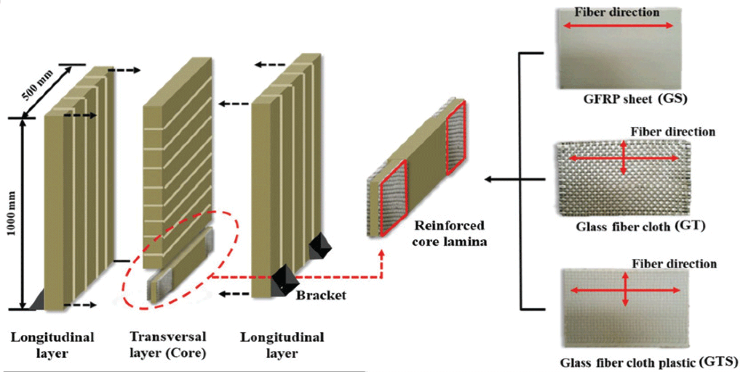
Lee et al. reported that the bond strength between GFRP and wood affects the performance of reinforced timber joints using glass fiber-based reinforcement (2017). Thus, the adhesives between core lamina and glass fiber-based reinforcement were determined through the results of previous studies. The lamina and GFRP sheet or glass fiber cloth plastic were bonded with polyvinyl acetate (PVAc) adhesive while the lamina and glass fiber cloth were bonded with phenol-resorcinol formaldehyde (PRF) adhesive (Lee et al., 2019; Kim and Hong, 2011).
For CLT fabrication, 100 (b) × 30 (t) mm artificially dried larch laminae (Larix kaempferi Carr.) were used. The laminae were combined randomly regardless of their E-rating. For the reinforced CLT walls, glass fiber reinforced core laminae were inserted in the support connection instead of ordinary core laminae. All the CLT walls were laminated with PRF adhesive. The application amount was 300 g/m2, and the pressing pressure was 0.98 MPa (Song and Hong, 2016). The fabricated CLTs were cured at room temperature for 3 days, and then processed to the final size of 500 (w) × 1000 (h) × 90 (t) mm, with a 1:2 aspect ratio. The CLT walls were fabricated in four types: unreinforced Series-Con and reinforced Series-GS, Series-GT, and Series-GTS (reinforcement volume ratio: 3%). Two specimens were fabricated for each series, one for the monotonic test and one for the cyclic test.
Self-made brackets were used for the connection the CLT walls with metal frame floors. The metal bracket was made of steel plates that were 5 mm thick, 90mm high and 100mm wide. Two 12 mm high-tensile bolts were used to connect the bracket and the metal frame floor, and 14 3.2 (d) × 64 (l) mm screws were used to connect the bracket to the wall. One bracket was placed at each end of the front and back of the CLT walls (4 brackets in all). The behavior of the timber walls for the horizontal shear load appears in three cases, as follows (Dujic et al., 2006):
Case 1: Racking behavior, which occurs when the wall is free from the vertical load (racking behavior);
Case 2: Mixed behavior of shear and racking phenomena, which occurs when a vertical load is applied to the top of the wall; and
Case 3: Full shear behavior, which occurs when the wall is embedded in a rigid body frame.
In this study, the behavior of the reinforced CLT walls under a horizontal load was observed as the racking failure of case 1.
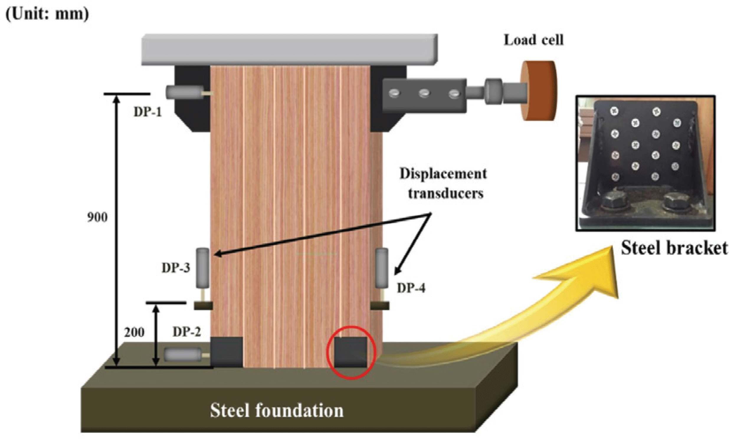
The horizontal shear test for CLT walls was performed in accordance with KS F 2154. As shown in Fig. 2, displacement transducers (CDP-50) with a 50 mm maximum capacity were installed at 50 mm from the top (DP1) and bottom (DP2) on the other side of the load cell. The displacement caused by uplift was measured by installing the displacement transducers at 200 mm from the support on the right and left sides of the wall (DP3, DP4). The displacement of the transducer was measured using a data logger (TDS-302) according to the changing load.
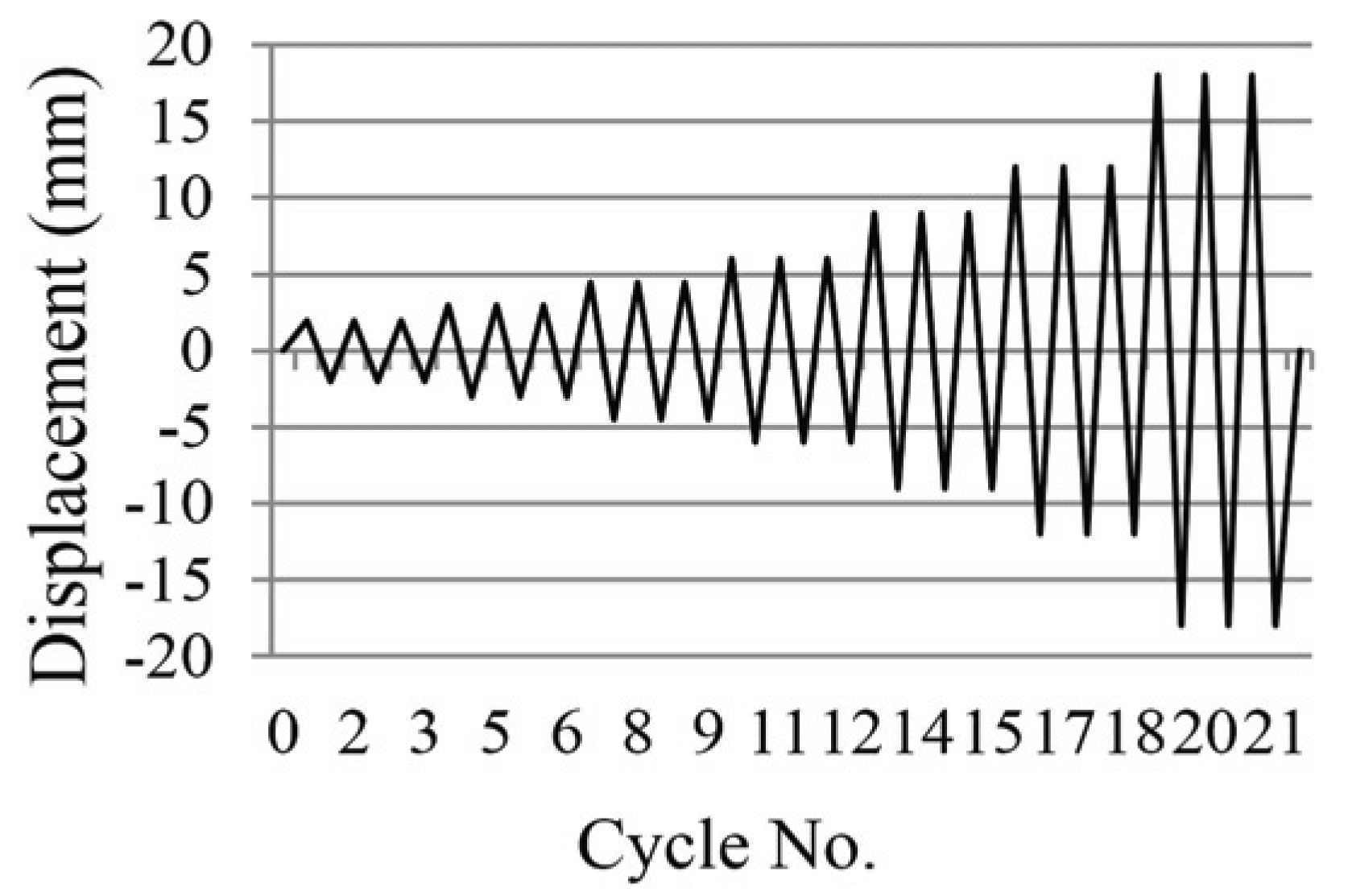
For the cyclic loading schedule, the 1/450, 1/300, 1/200, 1/150, 1/100, 1/75, and 1/50 rad. drift angles were converted into horizontal displacements using equation (1). Three cyclic loads were applied in each horizontal displacement interval (Fig. 3). The loading speed of the monotonic and cyclic tests was 10 mm/min.
Where:
γ = Drift angle (rad.)
ΔDP1 = Displacement of DP1 (mm)
ΔDP2 = Displacement of DP2 (mm)
H = Distance between DP1 andDP2 (mm)
3. RESULTS and DISCUSSION
For Series-Con, variations in load and displacement continued to occur as the screws were pulled out from the CLT simultaneously with the deformation of the bracket from the yield section until the maximum load. As shown in Fig. 5, no failure of the CLT occurred. As shown in Fig. 4, the horizontal shear strength behavior of Series-GS against a monotonic load was generally not much different from that of Series-Con. The initial stiffness, however, was approximately 11.8% lower than that of Series-Con, which seems to have been caused by the adhesive (Table 1). Series-Con was fabricated using only resorcinol adhesive, which has high hardness after curing. By contrast, PVAc adhesive, which was used when inserting and bonding reinforced core lamina into the bottom lamination of Series-GS, has relatively low hardness after curing. The failure mode of Series-GS was similar to that of Series-Con, but some screws of the Series-GS were fractured by the reinforcement GFRP sheet.
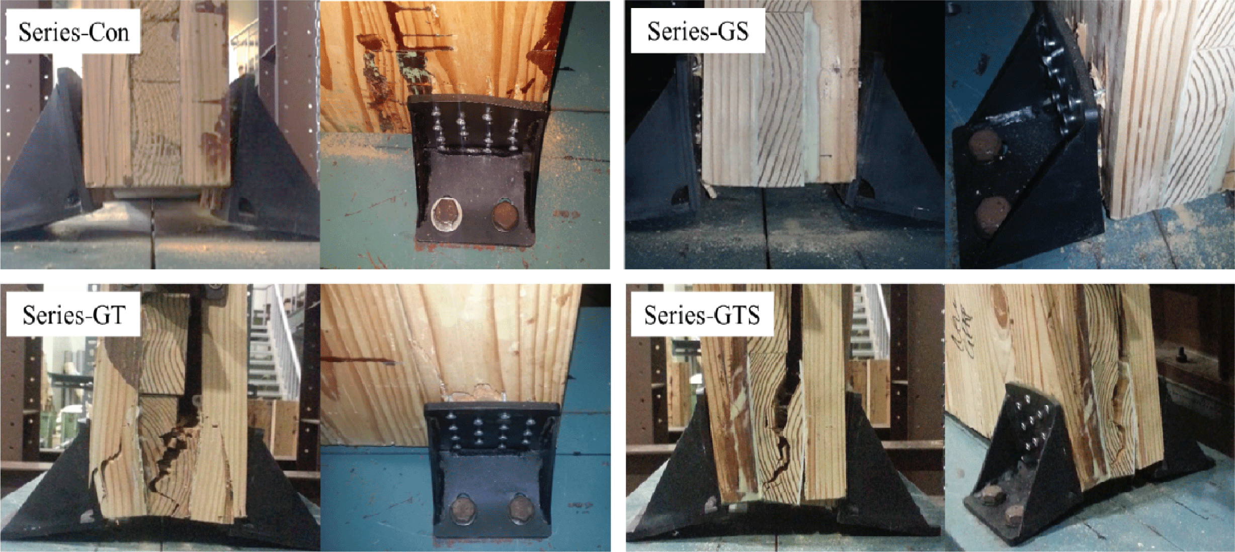
Series-GT, with textile-type reinforcement, was fabricated only with resorcinol adhesive (including the core lamina reinforcement), in the same way as Series-Con. Thus, the initial stiffness of Series-GT increased by 23.5% compared to that of Series-Con due to the high stiffness of resorcinol after curing and textile-type reinforcement. However, the textile-type reinforcement showed a low maximum capacity in contrast to its high stiffness. Consequently, the maximum and yield loads of Series-GT were lower by 11.8 and 28.6%, respectively, compared to those of Series-Con. The failure mode of Series-GT was also different from those of the two other series: the CLT adjacent to the bracket failed.
The maximum load of Series-GTS was not much different from that before reinforcement, but for the same reason as with Series-GS, the initial stiffness was 17.6% lower than that of Series-Con. The yield load of Series-GTS increased by 16.3% compared to that of Series-Con. It was determined that the reinforcement with glass fiber cloth inside the GFRP sheet showed higher reinforcement performance. The failure mode of Series-GTS was very similar to that of Series- GT, and the lamina in the connection zone failed significantly. Meanwhile, in the compressed connections of all monotonic specimens, only a little deformation of the brackets was observed, and no other failure modes were observed.
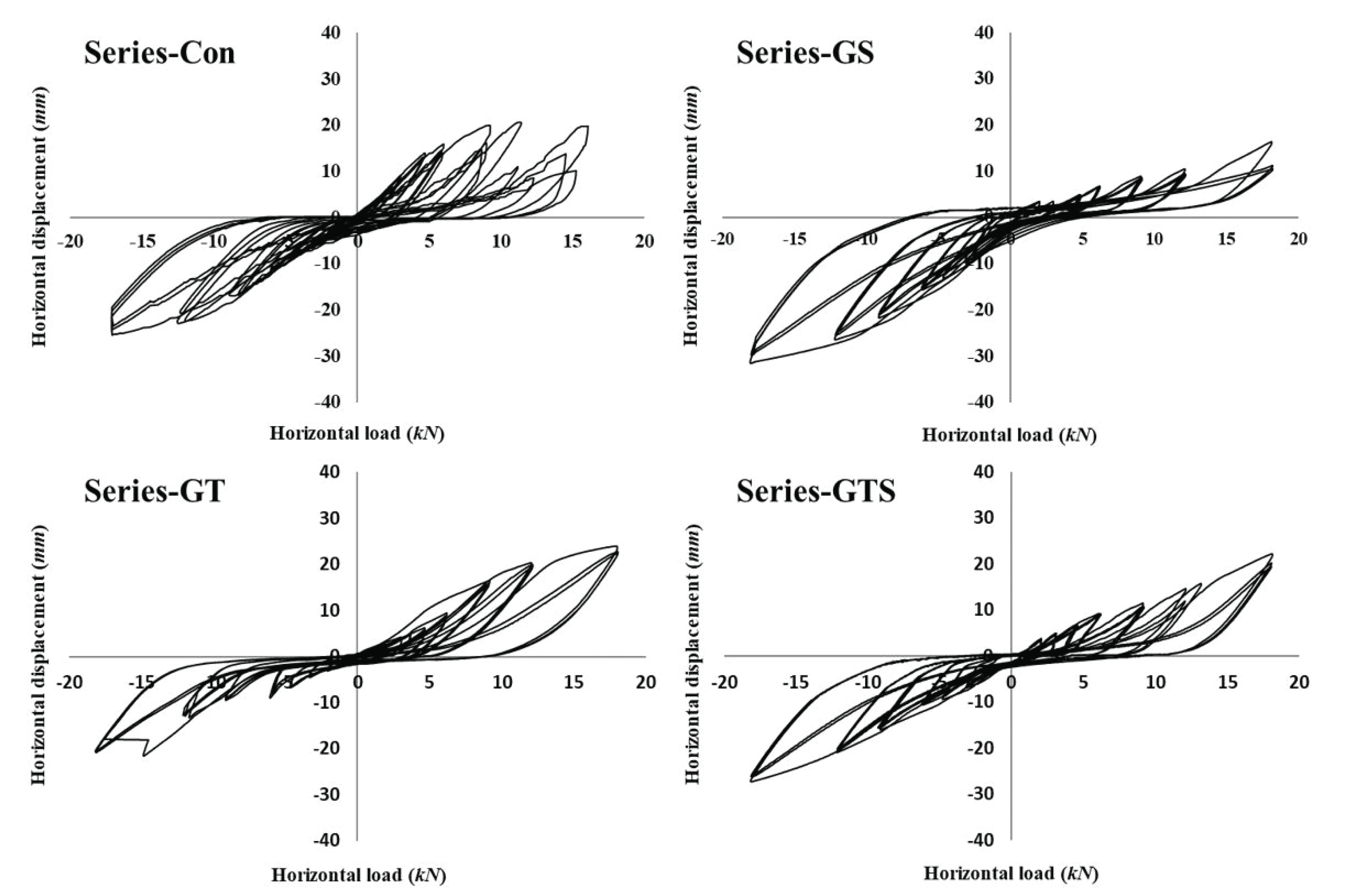
Fig. 6 shows the hysteresis loops of CLT walls. The results of the horizontal shear test of CLT walls under cyclic loads are as follows;
In the case of Series-Con, the maximum strength was 7 kN at 1/75 rad. of a positive load, and increased up to 25.4 kN at 1/50 rad. of a negative load.
For Series-GS, low strength was measured in each displacement section because the uplifted reinforced CLT connection had insufficient integrity. This result indicates that more precise processing is required in the production of the reinforced CLT connection system. Consequently, low maximum strength at 1/50 rad. was measured at 16.4 kN. Under a negative load, however, normal loading occurred, and the maximum strength was 31.6 kN, 24% higher than the maximum strength of Series-Con.
For Series-GT, the maximum strengths measured at 1/50 rad. of the positive and negative loads were 24.0 and 21.6 kN, respectively. Furthermore, the maximum strengths of Series-GTS measured at the last displacement section of 1/50 rad. were 22.2 and 27.3 kN, respectively. In the hysteresis loops of the two specimens, the maximum strength was not much different from that of Series-Con. The fact that the maximum strength of Series-Con was recorded at 1/75 rad., however, and decreased at 1/50 rad., is distinctly different from the fact that for Series-GT and Series-GTS, the maximum strength was measured at the last displacement section of 1/50 rad. This suggests that the reinforcement prevents strength degradation of CLT connections. No significant failure modes were observed at all CLT connections until 1/50 rad.
Timber structures connected using metal fasteners are sensitive to the strength degradation of the connection under a cyclic load. Consequently, strength degradation is an important parameter for checking the resistance capacity in seismic motions (Sheikhtabaghi, 2015; Pozza et al., 2014). Strength degradation (ΔF) refers to a load reduction at a certain displacementcontrol cyclic loading level (DIN 12512, 2002). In this study, strength degradation was calculated based on the difference between the maximum load of the first cycle and the maximum load of the third cycle in the same displacement section (Eq. 2).
Where:
ΔF = Strength degradation
F1 = Force at first cycle,
F3 = Force at third cycle
Consequently, as shown in Table 2, in the case of Series-Con, less than 10% strength degradation was found until 1/200 rad., but it increased thereafter, and the strength was degraded by 59.3% at 1/75 rad. In the case of Series-GS, the strength degradation measured at the low displacement section of 1/300 rad. was 24.1%, but the strength degradation considerably decreased in the later sections due to the reinforcement effect. For Series-GS, considerable strength degradation occurred at the maximum displacement section of 1/50 rad., as with Series-Con. In the case of Series-GS, a bearing failure occurred in the core lamina reinforced with GFRP sheet due to the screw in the first cycle. In contrast, the strength degradation of Series-GT and Series-GTS was less than 10% on average, indicating excellent performance. These results suggest that the reinforcement containing textile-type glass fibers minimizes strength degradation.
The graph on the right in Fig. 7 shows the backbone curves of the CLT walls drawn by connecting the maximum loads representing the cyclic on the hysteresis loops, as shown in the graph on the left. Series- Con has high CLT connection integration because it was fabricated without inserting a reinforced core lamina made of a heterogeneous material in the fabrication process. This fabrication process showed high stiffness in the early displacement section compared to the two other series, but the stiffness decreased sharply from 1/100 rad. By contrast, the measured stiffness of the reinforced CLT walls was lower than that of Series-Con in the initial displacement section owing to the low integration of the CLT connection and the use of PVAc. The degree of stiffness was maintained, however, as the displacement increased. In particular, Series-GS showed the highest stiffness in every displacement section during loading.
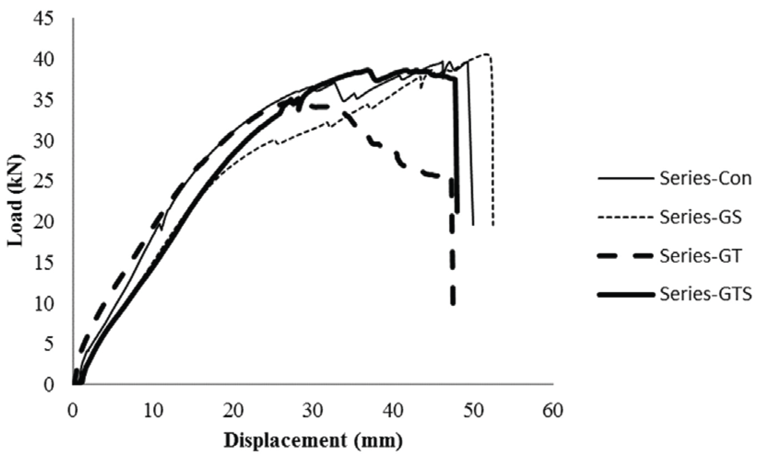
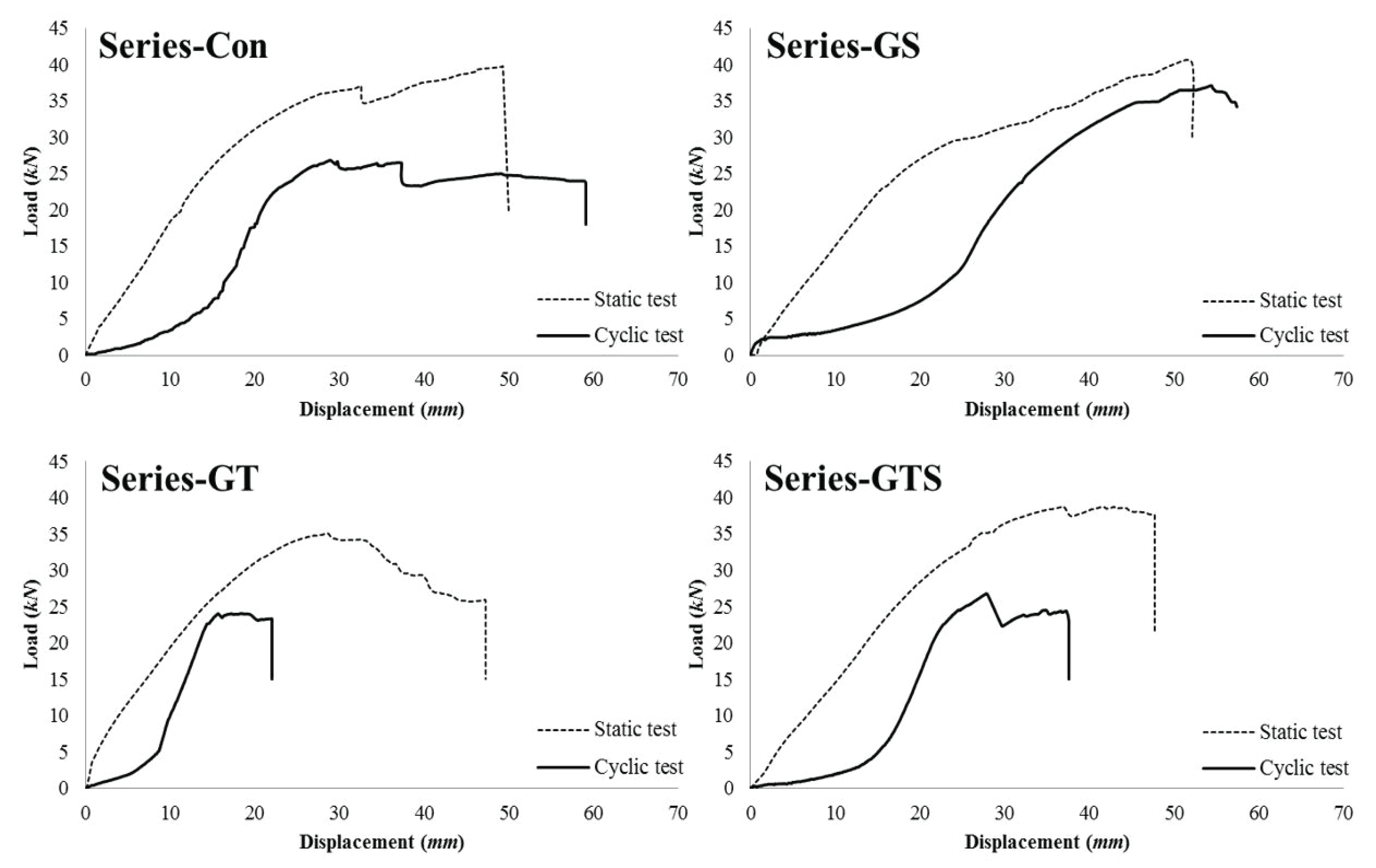
The processing type of the connection and the material characteristics of the connector determine the hysteresis. Therefore, the residual strength of the CLT walls that have been tested for a certain displacement section will be appropriate for identifying the strength properties of walls according to the connection type. The residual strength of the CLT walls was verified by applying a positive load until failure after applying cyclic loads for the last displacement section of 1/50 rad. Fig. 8 shows the load-displacement curve for the monotonic and cyclic tests for the CLT walls. The strength properties for the cyclic tests are outlined in Table 3. The ductility ratio was calculated using the of the load-displacement curve, as shown in Equation (3). The calculated ductility ratios were classified according to the grades suggested by Smith et al. (2006).
Where:
Dmax = Ductility ratio,
Δmax = Dispacement at maximum force,
Δyield = Dispacement at yield point
Among the reinforced CLT walls in this study, Series-GS showed the highest residual strength: 37.1 kN, which is 38.4% higher than that of the Series-Con. A reduction rate was calculated using the difference portion in the maximum loads of cyclic and monotonic tests. The lowest reduction rate of 7.7% was found in Series-GS, which confirmed that Series-GS had better resistance performance against cyclic loads than the other reinforced CLT walls. Furthermore, the ductility ratio also increased by 38% compared to that of Series-Con. Hummel et al. reported that in the cyclic loading test of CLT walls, bracket failure and pull-out of the screws were mainly observed and the CLT sometimes failed when a rigid support (steel) was used. Comparatively, when CLT was used as support, pull-out of screws and bracket deformation mainly occurred (2013). In contrast to the failure of CLT attributed to the screws in the previous study, Series-GS and Series-GT showed ideal failure modes, in which only the brackets were displaced, without failure of the CLT or pull-out of the screws, as shown in Fig. 9 (Schneider et al., 2012; Nakashima, 2014). The results of such reinforced GFRP in timber joints have often been reported in previous studies as it inhibits the failure of wood (Lee et al., 2017; Song et al., 2017).

4. CONCLUSION
This study was conducted to improve the horizontal shear strength of CLT walls by reinforcing their connection zone using glass fibers. Below are the conclusions that were arrived at based on the results of the study.
Under a monotonic load, the reinforced CLT walls did not show greatly improved horizontal shear strength compared to non-reinforced CLT walls. The types of glass fiber-based reinforcement and adhesive used were found to influence the horizontal shear strength.
Under a cyclic load, the maximum strength of the CLT walls reinforced with a glass fiber reinforced plastic sheet decreased by only 7.7% compared to the maximum monotonic load. The result showed a distinct reinforcement effect because not only did the yield strength and ductility ratio increase; the failure mode also improved.
The fabrication process in which the reinforced core lamina made of a heterogeneous material is inserted in the bottom core lamina of CLT walls can cause stiffness degradation in the early loading level when compared to the non-reinforced CLT made of wood. This is due to low composite integration, so further research on the composite properties is required.
This work was a basic study on the CLT wall system with a reinforced connection lamina for the improvement of horizontal shear strength. Additional research is required for the improvement of the fabrication process and for application to real-scale CLT walls.

